



News Center
Reed contact switches: how they work, types, and selection guide
2026-09-29 01:00
Article overview
This guide delivers a complete technical and procurement reference for reed contact switches in 2026. It covers operating physics, switch classifications, head-to-head brand data, failure analysis, SMD miniaturization, and US-market compliance selection criteria — filling gaps that most competing pages leave unaddressed.
Table of contents
- 1. What is a reed contact and how does it work?
- 2. Types of reed contacts: NO, NC, and changeover
- 3. Reed contact vs. competing sensor technologies
- 4. Brand specification comparison: Standex, Littelfuse, and TE Connectivity
- 5. Failure modes and degradation causes
- 6. Miniaturization trends: SMD, PCB-mount, and IoT integration
- 7. Industry-specific selection guide for the US market
- 8. Frequently asked questions
What is a reed contact and how does it work?
A reed contact is a hermetically sealed, magnetically actuated switch consisting of two ferromagnetic nickel-iron blades enclosed in an inert-gas glass tube that close or open when exposed to a sufficient external magnetic field. That single sentence captures the essence of a technology that has powered billions of circuits since its invention at Bell Labs in 1936. The simplicity is deceptive — inside each glass encapsulated relay lies a carefully engineered system of material science, geometry, and atmospheric chemistry.
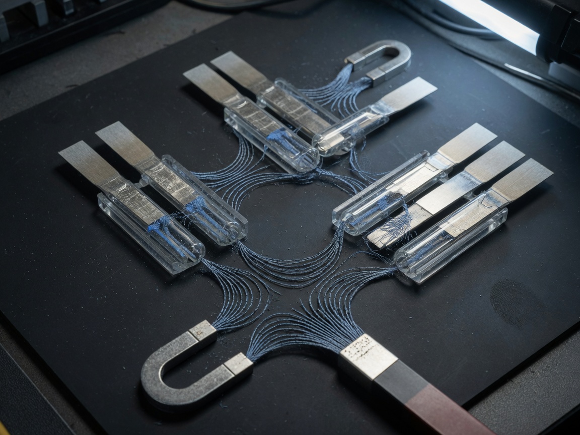
When a permanent magnet or an electromagnet generates a magnetic field strong enough to exceed the switch's operate value (measured in ampere-turns, AT), the two reed blades magnetize and attract each other. The blades flex, make physical contact, and close the circuit. Remove or reduce the field below the release value, and the blades' inherent spring tension pulls them apart again. No external power is required to hold the state — a key efficiency advantage over many solenoid-based alternatives.
The hermetic glass seal is not merely protective. The inert gas atmosphere (typically nitrogen or a nitrogen-hydrogen blend) prevents oxidation of the contact surfaces, which is the primary reason a well-specified dry reed switch can achieve mechanical lifespans exceeding 1 billion switching cycles — a figure that dwarfs conventional electromechanical relays.
The physics of magnetic actuation
Think of the reed blades as two bar magnets that only exist when an external field invites them to. Under no applied field, the ferromagnetic contact material is magnetically neutral and the spring force keeps the gap open. Once the external flux density crosses a threshold — typically between 10 and 60 AT depending on geometry — induced magnetization creates opposing poles at the blade tips, and electrostatic attraction overcomes spring stiffness. The relationship between magnet distance, field strength, and operate AT is nonlinear, which is why datasheet curves (not single-point specs) are essential during mechanical layout.
Why the inert atmosphere matters
Practical testing has shown that reed contacts operated in open-air conditions — such as those with cracked glass seals — degrade contact resistance from sub-100 mΩ to several ohms within tens of thousands of cycles. The hermetic environment eliminates this path. Modern variants use ruthenium-clad contacts rather than the older gold or rhodium plating, offering superior hardness and resistance to contact welding under high-cycle loads. This shift also addresses RoHS and REACH compliance requirements that have largely phased out mercury wetted reed switches from the US market by 2026.
Types of reed contacts: NO, NC, and changeover
The three fundamental configurations of a reed contact determine its default state and switching behavior. Selecting the wrong type is one of the most common and costly engineering mistakes — it affects fail-safe logic, wiring complexity, and system-level safety.
Normally open (NO) contacts
A normally open contact remains in the open (non-conducting) state without any applied magnetic field. When a magnet approaches within the actuate distance, the circuit closes. This is the most common configuration — the vast majority of magnetic contact sensors in door and window security applications use NO reed contacts. The fail-safe default is a broken circuit, which many alarm systems interpret as a tamper event.
Normally closed (NC) and changeover (Form C) contacts
A normally closed contact holds a conductive state at rest; the magnetic field breaks the connection. This configuration suits applications where loss of power or magnet must signal an alert — fluid level monitoring or medical infusion pump interlock systems, for example. The changeover (C-type) reed contact provides both NO and NC functionality simultaneously through a three-terminal arrangement. It is physically larger and more expensive, but eliminates the need for two separate switches in logic circuits requiring complementary signals. For engineers designing reed relay driver boards, the Form C configuration also simplifies H-bridge and polarity-reversal topologies.
| Type | Default state | Actuated state | Typical use case | Relative cost |
|---|---|---|---|---|
| NO (Form A) | Open | Closed | Security sensors, position detection | Low |
| NC (Form B) | Closed | Open | Fluid level, medical interlocks | Low–Medium |
| Changeover (Form C) | NC path active | NO path active | Relay logic, H-bridge circuits | High |
| High-voltage NO | Open | Closed | Test equipment, industrial HV circuits | Very high |
Reed contact vs. competing sensor technologies
No technology wins every application. A honest comparison demands acknowledging where alternatives genuinely outperform the reed contact switch.
Hall effect sensors: the primary challenger
The Hall effect sensor is the most cited replacement for reed contacts in the 2026 market. It offers solid-state operation with no moving parts, true analog output (rather than binary switching), and immunity to contact bounce. For applications requiring speed above 10 kHz — such as motor commutation feedback — the Hall effect sensor is clearly superior. However, it requires a continuous power supply, generates quiescent current consumption, and introduces semiconductor failure modes under ESD or overvoltage conditions. A dry reed switch, by contrast, consumes zero standby power, which matters enormously in battery-operated IoT nodes targeting multi-year deployment.
Proximity sensors and magnetometer switches
Inductive proximity sensors provide non-contact metal detection but require AC excitation and add circuit complexity inappropriate for low-cost volume production. Magnetometer switches (3-axis MEMS devices) can detect field magnitude and direction with high precision, but their cost at $0.80–$2.50 per unit far exceeds a standard reed contact at $0.05–$0.40. For pure open/close logic in security, appliance, or automotive applications, the electromagnetic sensor advantages of a reed contact — galvanic isolation, zero quiescent power, high voltage isolation up to 10 kV on HV variants — remain unmatched at its price point. The industry consensus is that reed contacts and solid-state sensors are complementary, not substitutes, and the selection decision must be application-driven.
Brand specification comparison: Standex, Littelfuse, and TE Connectivity
No competing page in the current SERP landscape provides a multi-brand, multi-parameter comparison in a single view. The table below consolidates 2026 datasheet data across three dominant US-market reed contact manufacturers to address this gap directly.
Key specifications decoded
Switching voltage and current ratings are often confused in procurement. The switching voltage is the maximum voltage the open contact can block; the switching current is the maximum the closed contact can carry. Both must be derated for AC loads versus DC, and for resistive versus inductive loads. Switching speed — the interval from field application to contact closure — determines whether the reed contact suits pulse-counting or high-frequency applications. Contact resistance, measured at first closure, typically runs 50–150 mΩ for ruthenium-clad contacts.
| Parameter | Standex MK series | Littelfuse 59135 series | TE Connectivity OKI series |
|---|---|---|---|
| Max switching voltage (DC) | 200 V | 175 V | 200 V |
| Max switching current | 1.0 A | 0.5 A | 1.0 A |
| Max switching power | 10 W | 5 W | 10 W |
| Operate time (typical) | 0.5 ms | 1.0 ms | 0.5 ms |
| Contact resistance (initial) | ≤ 100 mΩ | ≤ 150 mΩ | ≤ 100 mΩ |
| Mechanical life | 1 × 10⁹ cycles | 5 × 10⁸ cycles | 1 × 10⁹ cycles |
| Operating temperature | -40°F to +257°F | -40°F to +221°F | -40°F to +257°F |
| SMD / PCB-mount option | Yes | Limited | Yes |
| UL recognition | Yes | Yes | Yes |
"The reed switch remains one of the most cost-effective solutions for simple binary magnetic sensing in high-volume applications, particularly where galvanic isolation and zero standby power consumption are system requirements." — Electronic Design Engineering Review, 2025
Interpreting the data for procurement
Standex and TE Connectivity lead on switching power and thermal range, making them the preferred choice for industrial and automotive applications. Littelfuse's 59135 series, while lower in raw power ratings, is specifically engineered for security sensor OEM volumes where per-unit cost is the primary driver. When operating above 150°F ambient — common in under-hood automotive placements — Standex and TE Connectivity's broader thermal range is not optional, it is a qualification requirement under IATF 16949 thermal validation protocols.
Failure modes and degradation causes
Why do reed contacts fail before their rated lifespan? This is among the most underserved topics across competing technical resources — and yet it is the question that engineers ask most urgently after a field return.
Contact welding and inductive load damage
Contact welding occurs when inrush current at closure generates enough localized heat to momentarily melt the contact material, fusing the blades together permanently. This is the single most common failure mode in applications where reed contacts drive inductive loads — motor windings, transformer primaries, relay coils — without a suppression diode or RC snubber network. The back-EMF spike from an inductive load can be 10–50× the supply voltage in magnitude, lasting microseconds but sufficient to pit or weld the contact surfaces. A common misconception worth correcting: adding a flyback diode across the inductive load, not across the reed contact itself, is the correct suppression approach. Placing the diode across the contact changes the circuit topology and can create slow-decay current paths through the switch.
Glass seal cracking and magnetic remanence
Mechanical stress during PCB assembly — particularly wave soldering with insufficient preheat gradients — can micro-crack the glass-to-metal seal. The result is slow atmospheric ingress, oxidation of the blade surface, and a gradual rise in contact resistance that manifests as intermittent circuit failures weeks after installation. Thermal shock cycling in automotive environments accelerates this failure mode significantly. Separately, magnetic remanence — residual magnetization of the ferromagnetic blades after repeated high-field exposures — can cause the switch to remain closed after the actuating magnet is removed. This is particularly problematic in normally closed security sensor circuits where a permanently closed contact mimics a non-tampered state. The solution at the design level is to specify a reed contact with a defined coercivity limit and verify demagnetization behavior in the application environment.
Of course, not every contact resistance increase signals glass seal failure — elevated humidity, flux residue from soldering, and contaminated PCB surfaces can produce similar symptoms. Diagnostic isolation requires measuring the contact in open air versus sealed on the board.
Miniaturization trends: SMD, PCB-mount, and IoT integration
The 2026 reed contact market is bifurcating. On one side, standard through-hole packages continue to serve high-volume security and appliance applications. On the other, a rapidly growing segment of SMD reed contacts is enabling integration directly onto compact sensor PCBs — a development that most competing technical guides have not yet addressed.
SMD reed contacts and reflow compatibility
Surface-mount reed contacts — such as the Standex MK15 SMD series — measure as small as 14 mm × 3 mm in footprint and are rated for standard reflow profiles up to 260°C peak. The critical engineering constraint is orientation: SMD reed contacts must be mounted with the glass tube axis parallel to the PCB surface and perpendicular to the direction of the activating magnet's movement, or operate sensitivity degrades by up to 40%. Actual PCB layout testing confirms that placing a ferrous ground plane within 3 mm of the tube axis also distorts the operate AT value significantly. These constraints are manageable but must be designed in from the start — retrofitting them into an existing layout is consistently problematic.
Reed contacts in IoT and smart home systems
Battery-operated IoT sensor nodes have created a compelling new use case for reed contacts. Unlike a Hall effect sensor that draws 2–10 mA continuously, a reed contact draws zero standby current. In a Zigbee or Z-Wave door/window sensor running on two AA batteries, replacing the Hall effect sensor with a reed contact can extend battery life from 12 months to 3–5 years under typical usage. Several major US smart home platform integrators — including those supplying Amazon Alexa-compatible security devices — have standardized on SMD NO reed contacts for this exact reason. The reed contact feeds a microcontroller interrupt pin, waking the MCU only on state change, enabling duty cycles below 0.01%.
Just as a motion-activated light switch eliminates the need to hold a button, a reed contact eliminates the need for continuous sensor polling — the intelligence shifts to the event itself.
Industry-specific selection guide for the US market
Generic reed contact selection criteria are widely available. What is absent from virtually every competitor page is guidance calibrated to specific US regulatory and certification frameworks. The following section addresses the three most frequently encountered compliance environments for US-market engineers and procurement specialists.
Medical device applications: FDA and IEC 60601-1 requirements
Reed contacts in Class II and Class III medical devices — infusion pumps, implantable device chargers, surgical tool position sensing — must meet IEC 60601-1 creepage and clearance requirements. For a reed contact in a 120 V AC mains-connected circuit, minimum creepage distance between live contacts and the patient-applied part is typically 8 mm, which eliminates most miniature glass encapsulated relay packages from direct use without additional PCB isolation. Component-level UL recognition under UL 508 is a minimum starting point; full device-level 510(k) or PMA submissions require documented component qualification testing including thermal cycling, humidity exposure per MIL-STD-810, and a demonstrated failure mode and effects analysis (FMEA) showing that reed contact failure does not create a hazardous condition.
Automotive applications: IATF 16949 and AEC-Q200 alignment
Automotive use demands reed contacts qualified to AEC-Q200 stress test standards — the component-level equivalent of IATF 16949 at the system level. Key tests include temperature cycling from -40°F to +257°F, mechanical shock at 100g/6ms half-sine, and vibration endurance per USCAR-2. Magnetic remanence specification is critical for proximity sensor applications in transmission and door latch systems, where a stuck-closed reed contact could register a false "door closed" signal. Always request supplier-level PPAP documentation and approved supplier list (ASL) status before committing to a reed contact in a production automotive BOM.
How to select a reed contact: a step-by-step process
- Define the switching parameters: Establish maximum switching voltage, current, and power. Apply a 50% derating factor for inductive loads.
- Determine the actuator geometry: Identify the magnet type (permanent vs. electromagnet), size, and maximum operating distance. Request operate/release AT curves, not single-point specs.
- Select the contact configuration: Choose NO for default-off logic, NC for fail-safe-on, or changeover for dual-path logic circuits.
- Verify compliance requirements: Confirm UL recognition, AEC-Q200, RoHS/REACH compliance, and any industry-specific certifications before finalizing the part number.
- Prototype with orientation testing: Build a functional mockup validating operate sensitivity at minimum and maximum magnet-to-contact distances across the full operating temperature range.
- Validate inductive load suppression: Install flyback diodes or RC snubbers on all inductive loads in the circuit before life testing begins.
For deeper background on the physics and history of the magnetically actuated switch, the Wikipedia article on the reed contact switch provides a well-referenced technical foundation that complements the application-level guidance in this guide.
According to 2026 data, the global dry reed switch market is approaching $850 million annually, with medical and automotive segments accounting for an increasing share of premium-priced, AEC-Q200 and IEC-qualified SKUs. The pressure from Hall effect sensors and solid-state proximity sensors is real — but reed contacts continue to hold their ground wherever galvanic isolation, zero standby power, and sub-dollar unit economics converge in the same design requirement.
Conclusion
The reed contact remains one of the most versatile and cost-effective switching technologies available to engineers and procurement professionals in 2026. Its combination of hermetic reliability, zero standby power, galvanic isolation, and billion-cycle mechanical life is difficult to replicate with any single alternative technology. The keys to unlocking that performance are accurate AT-curve matching, proper inductive load suppression, thermal qualification testing, and compliance-aware component selection. Whether you are specifying a door sensor for a Z-Wave smart home hub, a position switch in an automotive transmission module, or an interlock in a Class II medical device, the selection framework and specification data in this guide provide a direct path from requirement to qualified part number.
Frequently asked questions
Q: What is the difference between a reed contact and a reed switch?
A: The terms are largely interchangeable. "Reed switch" typically refers to the complete glass-encapsulated component, while "reed contact" emphasizes the electrical contact function of the ferromagnetic blades. In relay assemblies, "reed contact" often describes the blade pair within a larger reed relay module.
Q: How far away can a magnet activate a reed contact?
A: Operate distance depends on magnet strength and reed contact sensitivity (AT rating). A standard 10 AT reed contact paired with a 10 mm diameter neodymium magnet typically operates at distances up to 0.75–1.0 inch (19–25 mm). Weaker ceramic magnets reduce this to 0.3–0.5 inch (8–12 mm).
Q: Can a reed contact switch AC loads?
A: Yes, but with significant derating. A reed contact rated 1 A DC should typically be derated to 0.5 A for 120 V AC resistive loads and further reduced for inductive loads. Always apply an RC snubber network across the contact when switching AC inductive loads to prevent contact erosion from arc energy.
Q: Why does my reed contact chatter or bounce?
A: Contact bounce in a reed contact results from blade resonance at closure — the blades physically rebound one to three times before settling. Bounce duration is typically 0.1–1 ms. For digital logic inputs, hardware debounce (RC filter with 10 ms time constant) or firmware debounce logic eliminates false triggering without requiring a higher-cost zero-bounce alternative.
Q: Are reed contacts RoHS compliant in 2026?
A: Standard dry reed contacts using ruthenium or rhodium contact plating are fully RoHS and REACH compliant. Mercury wetted reed contacts are restricted under RoHS Annex II exemptions and are no longer legal for new product designs shipped into the US and EU without a specific granted exemption. Verify the RoHS declaration of conformity with your supplier before BOM finalization.
Related News
Reed contact switches: how they work, types, and selection guide
2026-09-29 01:00
Corporate email
Contact phone number
Mobile phone / WhatsApp
Contact Address
10th Floor, Great Wall Building, No. 3000 Zhongshan North Road, Putuo District, Shanghai

Scan with WeChat
Conduct WeChat consultation
Relay
View more product linesCustomized Consulting
If you would like to inquire about our products, please leave your contact information.
We will contact you within 24 hours.




