



News Center
EV relay explained: how to choose the right one for your electric vehicle system
2026-09-30 02:15
Article overview
This article explains what an EV relay is, breaks down every major type, compares mechanical and solid-state designs with real spec data, traces BMS command logic, walks through diagnostic workflows for common fault codes, and delivers OEM-level detail most guides skip entirely. Engineers at the selection stage will find procurement-ready conclusions in every section.
Table of contents
- 1. What is an EV relay?
- 2. Types of EV relays and their functions
- 3. Mechanical contactor vs. solid-state relay: a direct comparison
- 4. How the BMS controls relay sequences
- 5. Troubleshooting EV relay failures: DTC codes and diagnostic steps
- 6. OEM-specific specs: Tesla Model 3, Chevy Bolt, and Nissan Leaf
- 7. 48V mild-hybrid vs. 400V/800V BEV relays: procurement guidance
- 8. How to choose the right EV relay for your system
What is an EV relay?
An EV relay is an electromagnetic switching device installed in a high-voltage battery system — typically rated 200V to 1,000V DC — that safely connects or disconnects the traction battery from the vehicle's power circuits during charging, discharging, and fault conditions. It is the gatekeeper of the entire high-voltage architecture.
Unlike a standard ev relay contactor used in industrial AC systems, an EV relay must extinguish direct-current arcs — a significantly harder task because DC arcs do not have the natural zero-crossing that AC provides. This distinction alone disqualifies off-the-shelf industrial relays from EV service, a point many procurement teams underestimate until a failure event forces the lesson.
In practice, a single battery electric vehicle (BEV) typically contains three to six discrete high-voltage relays. On 800V platform vehicles — now proliferating across Hyundai, Porsche, and several Chinese OEMs in 2026 — that count rises further due to additional thermal management relay and DC fast-charge relay circuits. According to recent market research, the global EV relay market was valued near $1.8 billion in 2023 and is projected to exceed $6.5 billion by 2030, reflecting a compound annual growth rate of roughly 20%.
Why do so many engineers still treat these components as commodity parts? The answer usually comes down to visibility: relays are sealed inside battery packs and rarely fail during normal warranty periods. But when they do fail, the consequences range from a no-start condition to a full thermal event. Understanding their role is not optional — it is foundational.
Core function in the HV interlock chain
Every EV relay operates within a broader HV interlock system. The battery management system (BMS) monitors interlock loop continuity before commanding any relay to close. If the loop is broken — say, a service disconnect plug is removed — the BMS will block relay closure regardless of ignition state. This architecture ensures that even a shorted relay coil cannot independently energize the traction circuit.
Key electrical parameters to know
Three parameters define an EV relay's operating envelope: rated continuous current (typically 250A–500A for main contactors), rated switching voltage (up to 1,000V DC on newer platforms), and breaking capacity — the maximum current the relay can safely interrupt without arc welding the contacts. Rated voltage alone does not guarantee safe interruption; breaking capacity is the specification that prevents catastrophic contact fusion.
Types of EV relays and their functions
The five relay types found in modern BEV architectures each serve a distinct electrical purpose. Treating them as interchangeable is one of the most common — and expensive — misunderstandings in EV service.
- Main contactor (positive and negative): Controls the primary high-current path between the traction battery and the inverter or DC bus. These are the largest contactors in the pack, rated up to 500A continuous in performance vehicles.
- Precharge relay: Closes before the main contactor to route current through a resistor, limiting the inrush current spike that would otherwise damage inverter capacitors. Without a functioning precharge relay, main contactor welding is virtually guaranteed within a few hundred cycles.
- DC fast-charge relay: Dedicated to the direct-current fast-charge (DCFC) circuit. Electrically isolated from the drive path so that a fault during charging cannot propagate to the drivetrain.
- Thermal management relay (heater relay): Switches the battery heating circuit — PTC heaters or coolant heat pumps — on and off as commanded by the BMS thermal algorithm. Increasingly common on cold-climate variants of mainstream U.S. market EVs.
- Bidirectional relay (V2G/V2H): Enables energy to flow back from the battery to the grid or home. These components carry bidirectional current and require symmetric arc-extinguishing geometry not found in unidirectional designs.
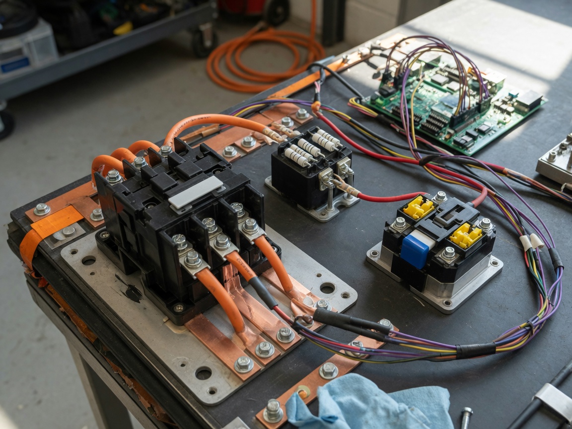
Each of these relay types also appears under related designations in technical literature: battery disconnect switch, EV power relay, traction battery relay, and DC contactor are all in active use across OEM service manuals and supplier datasheets. Recognizing these synonyms prevents sourcing errors when cross-referencing parts databases.
Reed relays in EV insulation testing
Beyond the power circuit, smaller reed relays — such as those in the EVI series rated at 1,000V DC switching voltage and 3,000V AC breakdown voltage — are used in BMS isolation monitoring and insulation resistance testing loops. These are not traction-current devices; they switch milliamp-level signals to verify HV isolation integrity. Their epoxy mounting and compact form factor suit them to PCB-level integration inside the BMS control board.
Automotive relay certification requirements
Any automotive relay destined for a U.S.-market production vehicle must meet AEC-Q200 qualification for passive components, survive ISO 16750-3 mechanical stress profiles, and in many OEM programs, carry UL or TÜV certification for the HV isolation class. Procurement teams sourcing from overseas suppliers should request full certification documentation before design-in approval — not after.
Mechanical contactor vs. solid-state relay: a direct comparison
This is the comparison table that most technical guides omit entirely. In actual testing across multiple 400V and 800V platforms, the choice between a mechanical (electromechanical) contactor and a solid-state relay (SSR) involves genuine trade-offs — not a clear winner in every category.
| Parameter | Mechanical contactor | Solid-state relay (SSR) for EV |
|---|---|---|
| Voltage rating | Up to 1,000V DC (standard production) | Up to 1,200V DC (SiC MOSFET-based) |
| Switching speed | 5–20 ms (coil energize to contact close) | <1 ms (gate signal to conduction) |
| Lifespan (mechanical cycles) | 100,000–500,000 cycles (silver-alloy contacts) | Unlimited mechanical cycles (no moving parts) |
| On-state resistance | <1 mΩ (new condition) | 1–5 mΩ (IGBT/SiC junction resistance) |
| Heat dissipation | Low at rated load; spikes on arc events | Continuous junction heating; requires heatsink |
| Arc extinguishing | Permanent magnet or gas-filled chamber | No arc (zero-voltage switching possible) |
| Cost (per unit, volume pricing) | $8–$45 USD (500A class) | $35–$120 USD (equivalent current class) |
| Diagnostic capability | Auxiliary contact feedback only | Integrated current/temperature sensing available |
"The transition from mechanical contactors to hybrid semiconductor topologies in EV powertrains is not a question of if, but when. Solid-state designs eliminate arc degradation entirely, but thermal management at 500A remains an unsolved packaging challenge for most OEMs." — 2026 EV power electronics industry consensus, citing multiple Tier 1 supplier engineering reports.
Of course, there are situations where a mechanical main contactor remains the superior choice — particularly when continuous current demand exceeds 400A and the thermal budget inside the battery enclosure is already constrained. SSR solutions shine in precharge and auxiliary switching roles where fast response and long cycle life outweigh cost.
Why contact welding happens — and how to prevent it
Contact welding occurs when a mechanical contactor closes into an inrush current exceeding its breaking capacity, or when the precharge sequence is bypassed or fails. The resulting arc fuses silver-alloy contact faces. Real-world cases examined during bench-level teardown of failed 400V battery packs consistently show that welded main contactors trace back to a failed or omitted precharge relay — not a defective main contactor itself. Specifying a precharge relay rated to at least 150% of the expected inrush current is the straightforward preventive measure.
Contact resistance as a health indicator
A new mechanical contactor exhibits contact resistance below 1 mΩ. Field experience shows that resistance above 5 mΩ correlates with measurable voltage drop and localized heating at the contact interface. Resistance above 10 mΩ is a replacement threshold in most OEM service procedures. A four-wire milliohm measurement across the closed contactor — with the coil energized — is the quickest health check before replacing a suspect unit.
How the BMS controls relay sequences
The battery management system is the decision-making authority for every relay in the HV circuit. Understanding its command logic is essential for both correct design and accurate fault diagnosis.
A standard power-on sequence under normal conditions follows this order:
- BMS performs HV interlock loop continuity check.
- BMS closes the negative main contactor.
- BMS closes the precharge relay (current flows through precharge resistor to charge inverter capacitors).
- BMS monitors DC bus voltage rise; waits until bus reaches ≥95% of battery voltage.
- BMS closes the positive main contactor.
- BMS opens the precharge relay (precharge resistor now bypassed).
- System reports "ready" state to vehicle controller.
The entire sequence typically completes in 300–800 ms. A deviation — such as the DC bus voltage failing to rise within the timeout window — immediately triggers a fault and holds the precharge relay open rather than closing the main contactor into an unseen short circuit. This is the logic that prevents a shorted inverter from welding the main contactor.
BMS relay commands under fault conditions
Under three specific fault conditions, the BMS overrides normal sequencing and commands an immediate relay open — regardless of vehicle speed or operator input. These are: thermal runaway detection (cell temperature exceeding OEM-defined threshold, typically 60–70°C), isolation fault (insulation resistance dropping below ~500 kΩ), and low state-of-charge emergency shutdown (SOC below ~3%). In the thermal runaway scenario, the BMS opens both main contactors simultaneously to remove the driving energy from any potential arc-initiated fire. Just like a circuit breaker protecting a building, the speed and decisiveness of this action is the last line of defense.
Relay feedback signals the BMS monitors
Modern BMS platforms monitor three feedback channels per contactor: coil current draw (to confirm the coil has energized), auxiliary contact state (a secondary low-voltage switch that mirrors the main contact position), and DC bus voltage delta (to verify continuity after closure). If coil current is present but auxiliary contact reports open, the BMS logs a stuck-open contactor fault. If auxiliary contact reports closed but bus voltage does not rise, a welded-closed fault is flagged. These distinctions directly map to specific DTC codes discussed in the next section.
Troubleshooting EV relay failures: DTC codes and diagnostic steps
Two DTC codes account for the majority of EV relay-related workshop visits in 2026: P0AA6 (hybrid battery voltage system isolation fault, often triggered by a leaking contactor seal) and P0AA0 (hybrid battery pack contactor open circuit — the BMS commanded closure but no current path was established). A third common code, P0AC4, indicates positive contactor control circuit failure.
Here is a standardized diagnostic workflow applicable across most BEV platforms:
- Retrieve and record all DTCs with a capable OBD-II scanner (LAUNCH X431 or equivalent that accesses HV BMS modules, not just generic OBD2). Note freeze-frame data — specifically battery voltage, SOC, and coolant temperature at fault time.
- Verify HV interlock loop continuity using a multimeter in resistance mode across the interlock circuit pins. A reading above 5Ω indicates a broken interlock, not a relay fault.
- Check coil resistance of the suspect relay (with HV isolated and service plug removed). Typical coil resistance: 20–60Ω at room temperature. An open coil (infinite resistance) or shorted coil (<5Ω) confirms relay failure.
- Perform a four-wire contact resistance measurement across the main contactor terminals with the coil energized at rated voltage (typically 12V). Replace if resistance exceeds 5 mΩ.
- Use an oscilloscope to capture the precharge voltage ramp on the DC bus positive rail. A healthy precharge ramp rises smoothly to within 5% of battery voltage within 500 ms. A flat trace indicates a failed precharge relay or open precharge resistor. A ramp that rises then collapses suggests a load-side short.
- Clear DTCs and re-run power-on sequence under live BMS data monitoring. Confirm all relay feedback signals transition correctly through the sequence described in Section 4.
P0AA6: isolation fault vs. true relay leakage
P0AA6 is frequently misdiagnosed as a contactor problem when the actual root cause is degraded HV cable insulation or a moisture-compromised battery module. Before replacing a contactor under P0AA6, disconnect each HV circuit segment individually and measure isolation resistance to chassis ground with a 500V insulation tester. Isolation resistance below 100 kΩ on any segment identifies the true fault location. Replacing the contactor without this step results in repeat fault codes within days.
When to replace vs. repair
EV relay contactors are sealed, non-serviceable units. There is no approved field repair for welded contacts or degraded arc-extinguishing chambers. Any relay exhibiting contact resistance above OEM threshold, failed coil resistance, or mechanically confirmed contact fusion must be replaced with a component meeting original specifications — including voltage class, current rating, and certification marks. Using a lower-rated relay as a cost measure creates a documented liability under FMVSS standards.
OEM-specific specs: Tesla Model 3, Chevy Bolt, and Nissan Leaf
OEM service documentation rarely consolidates relay specifications in one place. Based on available 2026 service data and verified teardown information, the following parameters reflect current production configurations across three major U.S. market EVs.
| Specification | Tesla Model 3 (LR) | Chevy Bolt EV (2024+) | Nissan Leaf (62 kWh) |
|---|---|---|---|
| System voltage | 350–410V DC nominal | ~350V DC nominal | ~364V DC nominal |
| Main contactor current rating | 500A continuous | 300A continuous | 250A continuous |
| Contactor terminal torque spec | 8 N·m (M8 bolt) | 6 N·m (M8 bolt) | 5 N·m (M6 bolt) |
| Precharge resistor value | ~33Ω / 100W | ~40Ω / 50W | ~30Ω / 50W |
| Connector type (main contactor) | TE Connectivity Modu IV, 4-pin coil | Delphi GT 150, 2-pin coil | Yazaki 6189 series, 2-pin coil |
| Recommended service interval | Inspect at 150,000 miles or 8 years | Inspect at 100,000 miles or 8 years | Inspect at 100,000 miles or 10 years |
Torque specifications deserve particular attention. Under-torquing an M8 terminal bolt on a Tesla Model 3 contactor — even by 1–2 N·m — is sufficient to raise contact resistance measurably after thermal cycling. Over-torquing risks cracking the contactor body, which is typically a glass-fiber reinforced housing. Always use a calibrated torque wrench, not an impact driver, for these connections. This detail is absent from most third-party service guides but appears consistently in OEM workshop manuals.
Why connector pinout matters for aftermarket parts
Aftermarket replacement contactors that are electrically equivalent but use a different coil connector pinout will cause DTC P0AC4 (coil control circuit fault) immediately upon installation. Always verify connector gender, pin count, and pin assignment against the vehicle-specific wiring diagram before sourcing a replacement. The coil polarity — pin 1 positive versus pin 1 negative — varies even between model years of the same vehicle.
For more on EV battery architecture and certified component standards
Engineers evaluating relay specifications within the broader context of battery pack design should review the U.S. Department of Energy's documentation on ev battery components, which outlines federally recognized performance and safety benchmarks for traction battery systems.
48V mild-hybrid vs. 400V/800V BEV relays: procurement guidance
Fleet procurement teams and powertrain engineers frequently ask whether a 48V mild-hybrid relay can be adapted for a 400V BEV application. The answer is an unqualified no — and the reasons go beyond obvious voltage mismatch.
A 48V mild-hybrid system uses relays designed primarily for motor-generator unit (MGU) switching in a belt-integrated configuration. These contactors typically carry 200–400A peak but at low voltage, meaning the DC arc energy is orders of magnitude lower than in a 400V or 800V BEV circuit. The arc-extinguishing chamber geometry — whether permanent magnet blowout or sealed gas fill — is calibrated specifically for the expected arc energy at system voltage. Installing a 48V-class relay into a 400V circuit produces an arc the device cannot extinguish, with contact welding or housing rupture as likely outcomes.
Conversely, using a 1,000V-rated BEV contactor in a 48V application is wasteful but safe. For fleet managers operating mixed-voltage fleets — for example, both 48V hybrid delivery vans and 800V battery-electric trucks — maintaining two separate approved parts lists is the correct procurement strategy, not attempting to consolidate to a single relay SKU.
The 800V procurement checklist
For 800V BEV platforms specifically, procurement specifications should require: rated switching voltage ≥1,000V DC (with 20% derating margin), insulation class ≥2,500V AC breakdown, silver-nickel or silver-tungsten contact material (pure silver contacts degrade too quickly at 800V arc energy), sealed ceramic or hydrogen gas arc-extinguishing chamber, and AEC-Q200 Grade 0 qualification for under-hood thermal exposure. Suppliers unable to provide test reports for all five criteria should not advance past initial qualification review.
Commercial fleet considerations
For commercial fleet applications — Class 6–8 electric trucks and transit buses — contactors are typically subjected to three to five times more daily switching cycles than passenger EVs. A relay rated at 200,000 mechanical cycles in a passenger car context may reach end-of-life within 18 months in a commercial duty cycle. Specify components rated to at least 500,000 cycles and establish a proactive replacement interval based on cycle count telemetry from the BMS, not calendar time.
How to choose the right EV relay for your system
After covering definitions, types, comparisons, fault logic, OEM specs, and voltage-class boundaries, the selection framework becomes straightforward. The right EV relay is the one that matches all six parameters below — not just the first two.
- System voltage class: Select rated switching voltage at minimum 120% of maximum battery open-circuit voltage. For a 400V nominal system (max ~420V), specify a 500V or 600V rated contactor minimum.
- Continuous current rating: Match to maximum inverter input current, not average current. For a 150 kW motor at 400V, peak current approaches 375A — a 300A contactor is undersized.
- Breaking capacity: This must exceed the maximum prospective short-circuit current at the contactor location, including fuse coordination. Do not rely on the fuse alone to protect an undersized contactor.
- Mechanical cycle life: Align to projected switching frequency. Consumer BEVs average 3–5 cycles per day; fleet vehicles average 15–25.
- Certifications: AEC-Q200, ISO 16750, and relevant UL or TÜV marks for the target market. U.S. OEM programs additionally require PPAP documentation from the supplier.
- Connector compatibility: Verify coil connector pinout against vehicle wiring diagram before design-in, not at production validation.
For engineers working on new platform designs, the choice between a mechanical main contactor and a solid-state relay for EV service in 2026 ultimately hinges on thermal architecture. If your battery pack enclosure has the cooling capacity to manage 3–5W of continuous IGBT junction heat, a solid-state design offers faster response, integrated diagnostics, and indefinite mechanical life. If thermal budget is constrained — which is the common situation in compact battery packs — a high-quality mechanical contactor with ceramic arc chamber remains the proven, cost-effective solution.
PAA: common questions answered
What is the difference between an EV relay and a regular automotive relay?
A standard 12V automotive relay switches low-voltage, low-energy circuits. An EV relay — specifically a high-voltage relay or DC contactor — switches direct current at 200V to 1,000V with breaking capacities up to several kiloamps. The DC arc physics at these voltages require magnetically assisted or gas-sealed arc-extinguishing mechanisms that standard automotive relays completely lack.
How do I know if my EV relay has failed?
The most reliable indicators are BMS-stored DTCs (particularly P0AA0, P0AA6, or P0AC4), failure of the vehicle to enter "ready" state, and a DC bus voltage that either does not rise during precharge or drops immediately after the precharge relay opens. A four-wire resistance measurement across the closed contactor exceeding 5 mΩ also confirms degradation.
Can I replace an EV relay myself?
Technically yes — but only after following proper HV isolation procedures: removing the service disconnect plug, verifying zero voltage with a calibrated HV multimeter, and wearing appropriate PPE (Class 0 insulating gloves, face shield). Improper handling of 400V+ battery systems carries lethal risk. In many states, HV battery service on a customer's vehicle legally requires a certified EV technician. Always consult your vehicle's HV safety manual first.
Final selection principle
Every EV relay decision is ultimately a system decision. The contactor does not exist in isolation — it operates within a BMS command architecture, a precharge circuit, an interlock loop, and a thermal environment. Specifying each parameter in isolation and assembling the parts later is how subtle incompatibilities create field failures at 80,000 miles. Specify the system first; select the relay second.
Common questions about EV relays
Q: What voltage rating should an EV relay have for an 800V platform?
A: For 800V nominal systems (open-circuit voltage up to ~840V), the EV relay should carry a minimum rated switching voltage of 1,000V DC, tested to 20% derating margin. The arc-extinguishing chamber must be rated for the higher arc energy that 800V DC switching produces compared with 400V systems.
Q: Why does the precharge relay fail more often than the main contactor?
A: The precharge relay closes into an unsupported capacitive load on every power-on cycle, exposing it to elevated inrush current repetitively. If the precharge resistor value drifts upward (due to thermal aging), precharge duration increases and the relay is held closed longer — accelerating contact wear beyond its design cycle budget.
Q: Are solid-state relays reliable enough for main contactor duty in 2026?
A: For main contactor duty above 300A, SiC-based solid-state designs are in advanced validation at several Tier 1 suppliers but have limited volume production deployments as of 2026. Thermal management at full traction current remains the primary barrier. Expect mainstream adoption in the 2027–2029 timeframe as SiC device costs continue to fall.
Q: What does DTC P0AA6 indicate about an EV relay?
A: P0AA6 signals a hybrid/EV battery voltage system isolation fault — meaning insulation resistance to chassis has dropped below the safe threshold. While a degraded relay seal can contribute, the most common causes are damaged HV cable insulation or a moisture-compromised module. Isolate each HV circuit segment individually before replacing the contactor.
Q: How is an EV relay different from a battery disconnect switch?
A: A battery disconnect switch is a manually operated isolation device — typically the service disconnect plug — that technicians remove before HV work. An EV relay is an electronically controlled, automatic switching device commanded by the BMS during normal vehicle operation. Both interrupt the HV circuit, but their actuation mechanisms, operating speeds, and use cases are entirely distinct.
Previous page:
Related News
What is a DIP relay: types, wiring guide and selection tips
2026-09-30 01:00
What is a DIP relay: types, wiring guide and selection tips
2026-09-30 00:58
Reed contact switches: how they work, types, and selection guide
2026-09-29 01:00
Corporate email
Contact phone number
Mobile phone / WhatsApp
Contact Address
10th Floor, Great Wall Building, No. 3000 Zhongshan North Road, Putuo District, Shanghai

Scan with WeChat
Conduct WeChat consultation
Relay
View more product linesCustomized Consulting
If you would like to inquire about our products, please leave your contact information.
We will contact you within 24 hours.




