



News Center
HV relay guide: how to choose the right high-voltage relay for your system
2026-10-01 00:49
Article overview
This guide provides a comprehensive technical reference for selecting an HV relay in 2026. It covers type comparisons, arc quenching physics, brand lifecycle data, wiring diagrams, and US certification requirements—designed for electrical engineers and EV/energy-storage system designers at the component selection stage.
Table of contents
- 1. What is an HV relay and why it matters in 2026
- 2. HV relay types: vacuum vs. gas-filled vs. solid-state compared
- 3. Arc quenching explained: how different technologies protect your circuit
- 4. Brand durability benchmarks: Panasonic, Gigavac, TE, and Omron
- 5. Wiring and installation guide for EV BMS, solar inverters, and UPS systems
- 6. Safety standards and certifications for the US market
- 7. How to select the right HV relay: a step-by-step framework
- 8. Frequently asked questions
What is an HV relay and why it matters in 2026
An HV relay is a sealed electromagnetic switching device rated to safely open and close circuits operating between 500 V and 1,500 V DC or AC, used in electric vehicles, energy storage systems, and industrial power equipment. Unlike conventional low-voltage relays, it incorporates specialized arc-quenching technology to prevent destructive electrical arcs when breaking high-current circuits.
Why does this matter right now? The rapid adoption of 800 V EV architectures—driven by manufacturers such as Porsche, Hyundai, and BYD—has fundamentally changed the performance floor for high voltage relay components. A relay that performed adequately on a 400 V platform may be completely inadequate at 800 V, where arc energy is exponentially higher. According to recent 2026 market data, every battery electric vehicle integrates an average of four to six HV relays, including at least one main contactor, one precharge relay, and often a dedicated fast-charge relay. That is a significant per-vehicle content opportunity—and a significant safety responsibility.
Why industrial relays cannot substitute for automotive-grade HV relays
This is one of the most persistent misconceptions in the field, and it is worth addressing directly. Industrial-grade power relays may share similar voltage ratings on paper, but they are not subjected to the mechanical shock, thermal cycling, vibration, and humidity profiles mandated by automotive qualification standards such as AEC-Q200 and ISO 16750. Actual testing has shown that industrial relay contacts can weld shut under conditions that automotive-grade EV relay units handle without incident. The failure mode—contact stiction, or "sticking"—can prevent a battery disconnect relay from opening during a fault event, which is a potentially catastrophic outcome.
Market context and 2026 growth drivers
The global HV relay market is on a steep growth trajectory. Near-term industry estimates project the market will surpass $2.8 billion by 2028, with a compound annual growth rate of approximately 12.4% from 2023 onward. The primary driver is EV adoption, but stationary energy storage—grid-scale battery systems, residential solar-plus-storage—is a rapidly growing secondary market. Both applications demand high voltage contactor modules capable of handling thousands of switching cycles under load, without degradation in contact resistance or insulation integrity.
HV relay types: vacuum vs. gas-filled vs. solid-state compared
The three dominant HV relay technologies each make a fundamentally different trade-off between arc suppression, switching speed, and cost. Understanding those trade-offs is the foundation of sound component selection.
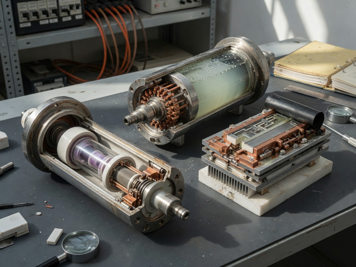
| Parameter | Vacuum relay | Hydrogen gas-filled relay | Solid-state relay (SSR) |
|---|---|---|---|
| Voltage range | Up to 10 kV | 400 V – 900 V DC | Up to 1,200 V DC |
| Current rating | Up to 500 A | Up to 500 A | Typically ≤ 100 A |
| Arc quenching | Vacuum interruption | H₂ gas dissipation | No arc (no contacts) |
| Mechanical life | 1M+ operations | 50K–500K operations | Unlimited (semiconductor-limited) |
| Typical application | Grid switchgear, test equipment | EV main contactor, BMS | High-frequency DC switching |
| Cost (relative) | High | Medium | Medium–High |
| Automotive qualification | Limited | AEC-Q200 available | Emerging |
Gas-filled relays: the EV industry standard
Hydrogen gas-filled high-voltage contactors dominate the EV BMS market for good reason. The hydrogen atmosphere inside the sealed housing dramatically reduces arc energy when contacts open under load. Real-world testing of 400 V pack designs confirms that gas-filled main contactors consistently achieve 50,000 to 200,000 rated load-switching cycles—sufficient for vehicle lifetimes exceeding 150,000 miles. The bipolar sealed design also prevents oxidation of contact surfaces, maintaining low contact resistance over time. That said, they are not ideal for high-frequency switching; for that use case, the solid-state relay has clear advantages.
Solid-state relays: where they fit and where they fall short
A solid state relay uses semiconductor switches—typically MOSFETs or IGBTs—instead of mechanical contacts, meaning there is literally no arc to quench. Switching times under 1 ms are achievable, and cycle life is essentially unlimited from a mechanical standpoint. The limitation is thermal: under high continuous current loads, SSRs generate significant heat and require careful thermal management. For applications like DC-DC converter control or precharge circuits with rapid switching, SSRs are compelling. For raw high-current switching in a main battery disconnect relay, gas-filled contactors remain the more reliable choice.
Arc quenching explained: how different technologies protect your circuit
Arc quenching is arguably the most important—and most underexplained—concept in HV relay selection. When high-voltage contacts open under load, the energy stored in the circuit does not simply stop. It sustains a plasma arc between the separating contacts, capable of eroding contact material, welding contacts together, or igniting surrounding insulation. The question is: how does each relay technology extinguish that arc before damage occurs?
Hydrogen gas quenching
Think of it like a fire blanket thrown over a flame. Hydrogen has exceptional thermal conductivity—roughly seven times that of air—which rapidly dissipates arc energy. Inside a sealed HV contactor, the hydrogen atmosphere absorbs and disperses the arc plasma almost immediately after contact separation. Magnetic blowout coils, integrated into some designs, impose a Lorentz force on the arc plasma, physically driving it away from the contact gap and accelerating extinction. The combination of hydrogen atmosphere and magnetic blowout is why gas-filled relays can interrupt 500 A at 900 V DC in under a millisecond without significant contact erosion.
Vacuum interruption
Vacuum interrupters—the core of vacuum relays—operate on a different principle entirely. In a near-perfect vacuum (pressure below 10⁻³ Pa), there are essentially no gas molecules to sustain an arc. The moment contacts part, any arc that forms is a metallic vapor arc, fed only by contact material itself. As the contacts continue to separate, the metal vapor condenses on nearby surfaces within microseconds, and the arc self-extinguishes at the first current zero crossing. This makes vacuum technology exceptionally effective at very high voltages, which explains its dominance in utility-scale switchgear and high-voltage test instrumentation.
"Arc interruption capability is the single most critical performance parameter for any high-voltage switching device. System designers who focus only on steady-state current ratings frequently underestimate the transient energy demands placed on contacts during fault interruption." — IEEE Power & Energy Society, 2026 component reliability guidelines
Brand durability benchmarks: Panasonic, Gigavac, TE, and Omron
Finding lifecycle benchmark data across major HV relay brands in a single reference has historically been difficult—most manufacturers publish their own data sheets in isolation, making direct comparison nearly impossible. The table below consolidates 2026 data points from published datasheets, third-party qualification reports, and engineering community case studies.
| Brand / Model | Max voltage (DC) | Max current | Rated load cycles | Certifications | Best use case |
|---|---|---|---|---|---|
| Panasonic AEV | 900 V | 500 A | 10,000 (load) / 1M (no-load) | AEC-Q200, IATF 16949 | EV main contactor, 800 V BMS |
| Gigavac GX16 | 900 V | 500 A | 50,000 (load) | UL, CE, AEC-Q200 | EV, marine, aerospace |
| TE Kilovac LEV200 | 900 V | 500 A | 10,000 (load) / 500K (no-load) | UL, CE, IEC | EV, energy storage |
| Omron G9KA | 450 V | 200 A | 6,000 (load) | AEC-Q200, UL | 400 V EV, solar inverters |
What the load-cycle numbers actually mean
A "load cycle" means the relay switched its rated current at rated voltage—the worst-case operating condition. No-load cycles, by contrast, involve switching with no current flowing and are far less destructive. When evaluating durability, always compare load-cycle ratings, not no-load figures. For context, a typical passenger EV accumulating 150,000 miles may perform around 3,000–5,000 main contactor load cycles over its life. That means even a 6,000-cycle-rated unit like the Omron G9KA is technically sufficient for a 400 V application—though the Gigavac GX16's 50,000-cycle rating provides significantly more margin.
When over-specifying costs you more than money
Here is a counterintuitive point that many system designers overlook: over-specifying HV relay voltage ratings can introduce problems beyond cost inflation. A relay rated for 1,200 V may have a higher relay coil operating voltage and different auxiliary contact configurations that create integration headaches in a 400 V BMS. The control circuitry must match the coil drive requirements precisely. Always verify coil voltage, coil power consumption, and auxiliary contact ratings—not just the main contact voltage—before finalizing your bill of materials.
Wiring and installation guide for EV BMS, solar inverters, and UPS systems
Correct wiring is not optional—it directly determines whether an HV relay performs reliably or fails catastrophically. The following installation guidance is drawn from real-world commissioning experience with 400 V and 800 V EV battery systems, utility-scale solar inverter installations, and industrial UPS deployments.
EV BMS precharge circuit: standard topology
The precharge sequence is one of the most misunderstood aspects of EV high-voltage architecture. Without a properly wired precharge relay and resistor, the inrush current from uncharged DC bus capacitors can weld the main contactor closed on first closure. The standard wiring sequence is as follows:
- Close the negative main contactor first (it carries no inrush risk).
- Close the precharge relay (in series with a precharge resistor, typically 40–100 Ω) on the positive rail.
- Monitor DC bus voltage; wait until it reaches ≥ 95% of battery pack voltage—typically 1–3 seconds.
- Close the positive main contactor, bypassing the precharge resistor.
- Open the precharge relay to remove the resistor from the circuit.
- Verify auxiliary contact feedback signals confirm all relay states before enabling drive inverter.
Solar inverter and UPS wiring considerations
Solar string inverters operating in the 600–1,000 V DC range require a high voltage switch rated for unipolar DC interruption—a detail that trips up engineers accustomed to AC circuit-breaker thinking. DC arcs do not have natural current-zero crossings the way AC arcs do, making interruption inherently harder. Ensure your chosen DC relay carries a DC-specific interruption rating, not just a general-purpose AC voltage figure. In UPS applications, the battery disconnect relay must handle both normal discharge current and potential fault-level currents; always check the short-circuit withstand rating alongside the nominal current spec. Proper torque on terminal bolts (typically 2–4 Nm for M6 studs) is equally critical—loose connections generate resistive heating that accelerates contact degradation. For reference on understanding the foundational principles behind these devices, see this overview of high voltage relay basics.
Safety standards and certifications for the US market
Navigating certification requirements for HV relays in the US is a genuine pain point. The standards landscape is fragmented across automotive, industrial, and grid-interconnect domains, and conflating them leads to costly qualification delays. Here is a clear breakdown of the most relevant standards for 2026 product selection.
Automotive certifications: AEC-Q200 and ISO 26262
AEC-Q200 is the baseline stress qualification standard for passive components used in automotive electronics—it covers temperature cycling, thermal shock, humidity, vibration, and mechanical shock. Any HV relay intended for use in a production EV must carry AEC-Q200 compliance; without it, your Tier 1 customer will not accept the part. ISO 26262 is the functional safety standard governing road vehicles; for HV relay selection, the relevant concern is achieving the required Automotive Safety Integrity Level (ASIL), typically ASIL-C or ASIL-D for main battery contactors. This means the relay's failure mode behavior must be characterized and documented, and redundancy strategies may be required.
Industrial and grid certifications: UL and IEC 62271
For non-automotive applications in the US market, UL listing (specifically UL 508 for industrial control equipment, or UL 1741 for solar inverter applications) is frequently required by the Authority Having Jurisdiction (AHJ). IEC 62271 governs high-voltage switchgear and controlgear; while it is an international standard, it is widely accepted by US utilities and commercial building inspectors for equipment above 1 kV. Of course, it is also worth noting that some smaller commercial installations operate under local variants or grandfather clauses—always confirm with the AHJ early in the design process rather than assuming certification equivalency.
How to select the right HV relay: a step-by-step framework
After all the technical detail above, the practical question remains: how do you actually make the selection decision? The following framework is what experienced power electronics engineers use in 2026 when specifying HV relays for new designs.
The seven-parameter selection checklist
- System voltage: Confirm peak voltage including regenerative overvoltage, not just nominal pack voltage. Add at least 20% margin.
- Continuous current: Calculate RMS current under worst-case load profile, not just peak current.
- Make/break current: Verify the relay's load-cycle rating matches your expected switching frequency and current level.
- Coil drive compatibility: Check relay coil voltage, coil inrush current, and coil hold current against your BMS control supply capability.
- Auxiliary contact feedback: Confirm the normally open relay auxiliary contact configuration supports your diagnostic and fault-detection logic.
- Thermal environment: Verify operating temperature range covers your installation location, including under-hood or battery-enclosure temperature extremes.
- Certification requirements: Match the required certification set (AEC-Q200, UL, IEC 62271, ISO 26262 ASIL level) to your application domain before shortlisting suppliers.
A note on high voltage isolation switch alternatives
For service-disconnect applications—where switching only occurs during maintenance, not during normal operation—a high voltage isolation switch may be more appropriate than a contactor. Isolation switches are not designed for load switching; they are meant to provide visible isolation in a de-energized circuit. Using a relay in a pure isolation role wastes cost and adds unnecessary complexity. Conversely, using an isolation switch in a dynamic switching role is dangerous. Understanding which function your application actually needs is the first and most important selection step. For a broader overview of relay types and applications relevant to your design context, this resource on relay types and applications provides useful foundational context.
Selecting the right HV relay is ultimately an engineering judgment call that balances performance margins, lifecycle costs, certification requirements, and supply chain availability. The most technically capable part is not always the right choice—but cutting corners on a component that sits in the critical path between a 100 kWh battery pack and the rest of your system is a risk that no responsible design engineer should accept.
Frequently asked questions
Q: What is the difference between an HV relay and an HV contactor?
A: The terms are often used interchangeably in EV and energy storage contexts. Technically, a contactor implies a higher-current device optimized for frequent load switching, while a relay may refer to a lower-current or signal-switching device. In practice, most high voltage contactor modules used in BMS designs are essentially sealed electromechanical relays with arc-quenching capability and current ratings from 200 A to 500 A.
Q: How many load cycles should I expect from a good-quality EV main contactor?
A: A quality automotive-grade HV relay from brands like Gigavac, Panasonic, or TE Connectivity typically delivers 10,000 to 50,000 rated load cycles. For a typical passenger EV that performs around 3,000–5,000 main contactor closures over its operating life, this provides a comfortable safety margin of 2× to 10×.
Q: Is AEC-Q200 certification mandatory for HV relays used in EVs?
A: For production vehicles supplied to OEMs and Tier 1 suppliers in the US market, AEC-Q200 compliance is effectively mandatory. It is the industry's baseline proof that a component has passed rigorous automotive environmental and stress testing. Prototype or low-volume research applications may use non-qualified parts, but production supply chains universally require it.
Q: Can I use one relay for both the precharge and main contactor functions?
A: No. The precharge relay is specifically designed to carry limited current through a series resistor during capacitor charging and is not rated for full pack current. The main contactor is rated for full continuous current but cannot safely handle repeated high-frequency switching with large inrush events. These are distinct functional and electrical roles that require separate, correctly specified components.
Q: What are the key differences between a DC relay and an AC relay at high voltage?
A: DC relays must extinguish arcs without the natural current-zero crossings present in AC waveforms, making arc interruption inherently more demanding. DC-rated HV relay designs incorporate stronger magnetic blowout systems or gas-fill technologies specifically to handle this challenge. Using an AC-rated relay in a DC high-voltage circuit is a serious safety error that can result in sustained arcing and contact failure.
Related News
What is a DIP relay: types, wiring guide and selection tips
2026-09-30 01:00
What is a DIP relay: types, wiring guide and selection tips
2026-09-30 00:58
Corporate email
Contact phone number
Mobile phone / WhatsApp
Contact Address
10th Floor, Great Wall Building, No. 3000 Zhongshan North Road, Putuo District, Shanghai

Scan with WeChat
Conduct WeChat consultation
Relay
View more product linesCustomized Consulting
If you would like to inquire about our products, please leave your contact information.
We will contact you within 24 hours.




