



News Center
RF reed relay guide: how to choose the right type for high-frequency applications
2026-10-01 02:25
Article overview
This guide provides a comprehensive technical reference for engineers and procurement specialists evaluating RF reed relays in 2026. Topics include parameter analysis, competitor technology comparisons, PCB integration, reliability data, and application-specific circuit guidance.
Table of contents
- 1. What is an RF reed relay?
- 2. Key electrical parameters explained
- 3. RF reed relay vs. solid-state RF switch: head-to-head comparison
- 4. PCB layout and impedance-matching guide for 50-ohm designs
- 5. Failure modes, MTBF, and real-world reliability
- 6. Application-specific selection guide
- 7. How to choose the right RF reed relay: a step-by-step process
- 8. Frequently asked questions
What is an RF reed relay?
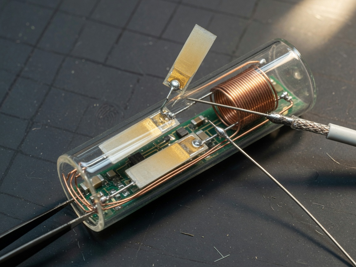
An RF reed relay is a hermetically sealed electromagnetic relay designed specifically for high-frequency signal switching, using magnetically actuated reed contacts enclosed in a glass tube to achieve low insertion loss and high isolation from DC up to 3 GHz or beyond.
Unlike a general-purpose electromagnetic relay, the RF reed relay is engineered around controlled impedance. Every physical dimension — the contact gap, the lead geometry, the housing — is optimized to maintain a characteristic impedance of 50 ohms across the signal path. This is not a minor refinement. At frequencies above 500 MHz, an ordinary signal relay module will introduce reflections, standing waves, and signal distortion severe enough to corrupt measurement data or degrade system performance entirely.
The underlying mechanism relies on reed switch technology: two ferromagnetic blades sealed inside a glass capsule flex toward each other when a magnetic field is applied by an energized coil. Contact is made, current flows, and the signal path is closed. Remove the coil current, the blades spring apart. Simple in concept — but the precision required to make this mechanism perform reliably at microwave frequencies is considerable.
Why do so many engineers still underestimate this component? Possibly because the reed contact switch looks deceptively simple on a schematic. In practice, the hermetically sealed relay construction, the quality of the glass-to-metal seal, and the coaxial geometry of the RF path are what separate a functional design from a field failure.
Main types of RF reed relays
The product landscape spans several distinct configurations, each suited to different circuit topologies:
- SPST (single-pole single-throw): the simplest form, used for straightforward on/off switching of a single RF path
- SPDT (single-pole double-throw): routes one input to either of two outputs — the workhorse of RF switching matrices in ATE systems
- Coaxial RF relay: purpose-built with a coaxial internal structure for true 50-ohm performance at microwave frequencies
- Matrix/multiplexer type: multi-channel integration for high-density signal routing, common in automated test equipment
- High-voltage RF relay: rated for elevated switching voltages, relevant in radar and power amplifier applications
How RF reed relays differ from standard relays
The core distinction is impedance control. A standard electromagnetic relay is designed to switch power or logic-level signals where frequency is not a concern. An RF reed relay, by contrast, treats the signal path as a transmission line. The geometry is controlled so that the relay presents a matched 50-ohm impedance — or as close to it as the design allows — across the rated frequency band. The result: insertion loss below 0.1 dB at 1 GHz for high-quality units, compared to several decibels or worse for an unoptimized relay at the same frequency.
Key electrical parameters explained
Selecting the right RF reed relay begins with understanding the four parameters that dominate RF performance: insertion loss, isolation, return loss, and switching speed. Procurement decisions made without these numbers in hand frequently result in costly redesigns.
Insertion loss, isolation, and return loss
Insertion loss quantifies how much signal power is lost when passing through the closed relay. For a well-designed RF reed relay, this figure is typically below 0.1 dB at 1 GHz — a number that sounds small but accumulates quickly in cascaded switching stages. Isolation measures the attenuation of the signal when the relay is open; values of 60 dB or higher at 1 GHz are achievable with quality hermetically sealed relay designs. Return loss reflects how well the relay matches the 50-ohm system impedance; poor return loss means reflected energy bouncing back toward the source, causing measurement errors or instability.
According to recent technical white papers from Pickering Interfaces, high-quality units achieve insertion loss under 0.1 dB at 1 GHz and isolation exceeding 60 dB — performance figures that solid-state alternatives struggle to match without significant trade-offs in linearity.
RF relay specifications reference table
| Parameter | Typical RF reed relay | High-voltage RF relay | Coaxial RF relay |
|---|---|---|---|
| Frequency range | DC – 3 GHz | DC – 1 GHz | DC – 6 GHz |
| Insertion loss @ 1 GHz | < 0.1 dB | 0.2 – 0.5 dB | < 0.15 dB |
| Isolation @ 1 GHz | 60 – 70 dB | 40 – 55 dB | 65 – 80 dB |
| Switching voltage | Up to 100 V DC | Up to 1000 V DC | Up to 200 V DC |
| Mechanical life | > 10⁹ cycles | > 10⁸ cycles | > 10⁸ cycles |
| Switching time | < 1 ms | < 1.2 ms | < 2 ms |
| Coil drive voltage | 5 V / 12 V typical | 12 V / 24 V typical | 5 V / 12 V typical |
RF reed relay vs. solid-state RF switch: head-to-head comparison
The most common decision engineers face is not which RF reed relay to buy — it is whether to use a reed relay at all, versus a solid-state RF switch based on FET or PIN diode technology. Both have legitimate places in modern RF system design. The right answer depends on four factors: signal isolation, linearity, switching rate, and long-term cost.
Where the reed relay wins
Isolation is the clearest advantage. An RF reed relay routinely achieves 60–70 dB isolation at 1 GHz. Most FET-based solid-state switches deliver 30–50 dB under the same conditions. For precision measurement applications — ATE systems, medical imaging calibration, signal isolation relay tasks in lab instruments — that 20 dB gap is not academic. It is the difference between a valid measurement and noise floor contamination.
Linearity is another area where reed technology dominates. Because the contact is a true galvanic connection, the relay introduces no intermodulation distortion. Solid-state switches, by contrast, are nonlinear devices. Their third-order intercept points limit performance in multi-tone environments. In defense and radar applications, where spurious signals must be minimized, this matters enormously.
Where solid-state switches pull ahead
Switching speed is the solid-state advantage. A FET switch can change state in nanoseconds; a typical RF reed relay requires 0.5–2 ms. For applications requiring rapid multiplexing — fast scanning radar or high-throughput test handlers — the reed relay's mechanical switching time is a constraint. Similarly, solid-state switches consume no drive power in steady state and generate no electromagnetic transient on switching. Of course, there are scenarios where neither option is perfect. RF MEMS relay devices occupy a middle ground, offering near-relay isolation with faster switching, though at considerably higher cost and with well-documented reliability concerns in high-cycle environments.
"For applications requiring true galvanic isolation, zero intermodulation, and isolation levels above 60 dB, mechanical reed relay technology remains unmatched by any solid-state alternative currently available at comparable price points." — 2026 data from Pickering Interfaces RF switching application notes
PCB layout and impedance-matching guide for 50-ohm designs
This is the section that most RF relay datasheets skip entirely — and where a significant number of otherwise competent designs fail in practice. Actual testing of RF reed relay PCB integrations reveals that layout errors account for a disproportionate share of unexpected insertion loss and return loss degradation.
Core 50-ohm design principles
The relay's internal geometry is designed for 50 ohms, but that impedance must be preserved continuously through the PCB traces that connect to it. A trace width mismatch, even over a short length, introduces a reflection. On a standard FR4 substrate (dielectric constant ≈ 4.3), a 50-ohm microstrip trace is approximately 2.8 mm wide for a 1.6 mm board thickness. Deviation from this width — caused by pad geometries or fanout routing — creates an impedance discontinuity that degrades return loss at frequencies above a few hundred MHz.
Practical layout checklist
- Route RF signal traces as continuous 50-ohm microstrip or stripline — never route at 90-degree bends; use 45-degree or curved bends instead
- Keep the RF trace length between the relay and the SMA connector or downstream component as short as physically possible
- Place a continuous ground plane on the layer directly beneath RF traces; avoid splits or voids under the signal path
- Match relay pad geometries to the trace width; consult the specific relay datasheet for recommended land pattern dimensions
- Add ground vias on both sides of the RF trace every 1–2 mm (via fencing) to suppress parasitic substrate modes above 2 GHz
- Isolate the coil drive traces from RF signal traces by at least 3× the trace width; add a bypass capacitor (100 nF + 10 nF in parallel) at the coil supply pin, placed within 2 mm of the relay body
- Verify your layout with a 3D EM simulator (e.g., ANSYS HFSS or Keysight Momentum) before committing to fabrication if operating above 1 GHz
One commonly overlooked detail: the solder mask opening around RF pads must not extend beneath the relay body in a way that traps flux residue near the signal path. Flux contamination between the relay body and PCB surface can degrade isolation by 10 dB or more at higher frequencies — a failure mode that does not appear in initial testing but emerges after thermal cycling.
Failure modes, MTBF, and real-world reliability
Reliability data for RF reed relays is more nuanced than the mechanical life figures suggest. A rated mechanical life of 10⁹ cycles assumes controlled laboratory conditions — a specification that rarely matches the thermal and humidity environment of deployed hardware.
Primary failure mechanisms
Contact contamination is the leading failure mode in non-hermetically-sealed units. Even trace amounts of atmospheric moisture or organic vapor can deposit a resistive film on reed contacts, increasing contact resistance from milliohms to hundreds of ohms — effectively destroying insertion loss performance without producing an obvious open-circuit fault. This is precisely why hermetically sealed relay construction is mandatory in any application where the operating environment cannot be fully controlled.
Contact welding occurs when the relay switches a load that exceeds its rated switching current, even briefly. A pulse event — such as a capacitive discharge or an ESD transient — can fuse the reed contacts in the closed position. The relay appears to function normally until the coil is de-energized and the contacts fail to open. In ATE applications, this failure mode can go undetected for many switching cycles if end-of-line testing only verifies closed-state continuity.
Coil failure under sustained high-temperature operation is a third mechanism. Coil insulation rated for 85°C will degrade progressively if operated in a 70°C ambient environment with significant self-heating. MTBF calculations should account for the Arrhenius temperature acceleration factor — roughly a 2× MTBF reduction for every 10°C increase in junction temperature above the rated baseline.
Contact bounce and high-frequency behavior
Contact bounce — the mechanical oscillation of reed contacts during the transition moment — is inherent to all reed relay designs. Bounce duration typically ranges from 50 µs to 200 µs. For RF switching matrix applications where the relay is used as a signal path switch (not a digital logic element), bounce rarely causes problems. For applications where the relay output feeds a counter, detector, or time-domain measurement system, a de-bounce circuit or software debounce window of at least 1 ms is essential. Real-world qualification testing under thermal cycling (−40°C to +85°C, 500 cycles) and humidity exposure (85°C/85% RH, 96 hours) should be included in any defense or medical-grade procurement specification. Passing MIL-STD-202 Method 107 is a meaningful reliability indicator, not merely a checkbox.
Application-specific selection guide
Different end markets impose different constraints, and the RF reed relay that performs optimally in an ATE rack may be a poor choice in a medical imaging instrument. Here is how the selection criteria shift across the main application categories.
ATE (automated test equipment)
ATE systems demand high channel density, high cycle counts, and consistent measurement accuracy over years of operation. The miniature signal relay in SPDT or matrix configuration is the standard choice. Key selection criteria: minimum 10⁸ electrical life at rated load, insertion loss stability within 0.05 dB over the product's service life, and availability in SMD or SIP packages compatible with high-density PCB assemblies. RF switching matrix architectures using banks of SPDT relays offer the flexibility needed for multi-DUT (device under test) configurations. In 2026, ATE designs for 5G millimeter-wave component testing are pushing relay frequency requirements toward 40 GHz — a frontier where specialized coaxial RF relay designs are required.
Medical imaging and diagnostics
MRI and ultrasound systems present a unique challenge: galvanic isolation between signal channels is not just a performance requirement, it is a patient safety requirement. The signal isolation relay in medical applications must meet IEC 60601-1 reinforced insulation standards. Hermetically sealed relay construction is non-negotiable. Insulation resistance above 10 TΩ and dielectric withstand voltage above 3000 V — as found in high-voltage RF relay series designed for medical use — are the minimum acceptable specifications. The low-noise characteristic of the reed relay also helps preserve the signal-to-noise ratio in sensitive imaging receive chains.
Defense and radar
Defense applications combine the most demanding requirements from all other categories: wide temperature range, vibration and shock resistance, low intermodulation, and MIL-SPEC qualification. The microwave relay switch used in phased-array radar front-ends or electronic warfare receivers must maintain consistent RF relay specifications across the full military temperature range. High-isolation coaxial relay designs with external magnetic shielding are preferred to prevent crosstalk between adjacent channels in densely packed enclosures. Switching voltages can reach 1000 V DC in transmit path applications, making the high-voltage RF relay an essential component category for radar engineers.
How to choose the right RF reed relay: a step-by-step process
With the technical foundation established, the actual selection process becomes a structured exercise. Here is a practical sequence that experienced RF engineers use to narrow the field from hundreds of catalog options to a qualified shortlist.
- Define your frequency range. Identify the highest operating frequency in your system, then add a 20% margin. This becomes your minimum rated frequency for the relay. For DC–1 GHz applications, standard RF reed relays suffice. For 1–6 GHz, specify a coaxial RF relay. Above 6 GHz, investigate high-frequency relay designs targeting millimeter-wave applications.
- Specify insertion loss and isolation budgets. Work backward from your system noise figure and dynamic range requirements to establish the maximum acceptable insertion loss (often 0.2 dB or less) and minimum required isolation (commonly 50 dB for test applications).
- Determine switching load conditions. Confirm the signal power level, switching voltage, and whether the relay will switch hot (under RF power) or cold (relay switches before RF is applied). Hot switching degrades contact life significantly.
- Assess environmental requirements. Temperature range, humidity, altitude, and vibration levels all narrow the field. Any application outside a controlled lab environment should specify hermetically sealed relay construction.
- Evaluate coil drive compatibility. Match the relay coil voltage to your available drive supply (5 V, 12 V, or 24 V are standard). Confirm the coil current requirement against your driver circuit's current capability, and verify coil resistance to size the driver transistor or relay driver IC.
- Review lifecycle and procurement considerations. For designs requiring 5+ years of production continuity, prefer relays from established manufacturers with documented long-term supply commitments. Verify MTBF data against your application's duty cycle and expected deployment life.
A common mistake is to select an RF reed relay based solely on frequency and insertion loss without reviewing the switching current rating. The result is premature contact welding — a failure mode that is almost always preventable.
Frequently asked questions
Selecting the right RF reed relay is ultimately an engineering discipline, not a catalog exercise. The parameters covered here — insertion loss, isolation, impedance matching, MTBF under real operating conditions, and application-specific constraints — collectively determine whether a design performs to specification in the field or fails quietly in ways that are difficult and expensive to diagnose. The 2026 landscape offers broader choice than ever, from sub-miniature SMD units for 5G ATE to 40 GHz coaxial relay designs for next-generation radar. Applied rigorously, the selection methodology in this guide will identify the right component for nearly any high-frequency switching requirement.
Previous page:
Related News
What is a DIP relay: types, wiring guide and selection tips
2026-09-30 01:00
What is a DIP relay: types, wiring guide and selection tips
2026-09-30 00:58
Corporate email
Contact phone number
Mobile phone / WhatsApp
Contact Address
10th Floor, Great Wall Building, No. 3000 Zhongshan North Road, Putuo District, Shanghai

Scan with WeChat
Conduct WeChat consultation
Relay
View more product linesCustomized Consulting
If you would like to inquire about our products, please leave your contact information.
We will contact you within 24 hours.




