



News Center
Magnetic contact switch buying guide: types, wiring tips, and how to choose the right one
2026-09-25 01:00
Article overview
This guide provides a comprehensive technical and commercial breakdown of the magnetic contact switch — from core definitions and product types to wiring diagrams, material compatibility, industrial use cases, and step-by-step troubleshooting. Written for security installers, DIY homeowners, and procurement engineers who need accurate specification data to make a confident purchasing decision.
Table of contents
- 1. What is a magnetic contact switch?
- 2. Types of magnetic contact switches
- 3. NC vs. NO vs. SPDT wiring
- 4. Gap distance tolerance by material
- 5. EOL resistor wiring for supervised loops
- 6. Industrial and harsh-environment applications
- 7. Troubleshooting false alarms
- 8. How to choose: buyer's checklist
- 9. FAQ
What is a magnetic contact switch?
A magnetic contact switch is a two-part proximity sensor consisting of a permanent magnet and a reed switch (or Hall-effect sensor) that opens or closes an electrical circuit when the magnet moves within or beyond a set operating distance. In plain terms: one half mounts on the door or window, the other on the frame. When the door opens, the gap widens, the magnetic field weakens, and the circuit changes state — triggering whatever alarm or automation system is connected downstream.
According to 2026 market data from MarketsandMarkets, the global magnetic sensor market is valued at approximately $4.2 billion, growing at a CAGR of 7.2%. Within the security segment, roughly 65% of all door and window detectors rely on magnetic contact switches as their primary sensing element (IHS Markit). That ubiquity is well-earned: these devices are passive, require no power at the sensor itself, have no moving mechanical parts subject to wear, and deliver reliable binary state detection at a very low cost per point.
Understanding the underlying technology matters before you buy. The classic magnetic reed switch technology uses two ferromagnetic contacts sealed inside a glass envelope filled with inert gas. When a magnet approaches, the contacts flex and touch — or separate, depending on the circuit configuration. Hall-effect variants replace the mechanical contacts with a semiconductor, offering longer cycle life and better vibration resistance, though at a higher unit cost. For most residential and light-commercial alarm applications, the traditional reed switch remains the dominant choice.
Why is this the starting point for any alarm system?
Every entry-point detector, burglar alarm sensor, and door alarm system needs a reliable way to sense whether a protected opening is closed or breached. The magnetic contact switch solves this with zero complexity at the sensing point — no optics to fog up, no microwave emissions, no PIR dead zones. It is, in a sense, the simplest possible detector: a gap sensor that measures one variable (distance) and outputs one signal (open or closed). That simplicity is its greatest strength, and also the source of most installation errors when buyers do not understand the nuances of gap tolerance and wiring logic.
Core components at a glance
- Actuator (magnet): mounts on the moving element (door, window, gate)
- Switch body (reed or Hall sensor): mounts on the fixed frame
- Housing: plastic (ABS/nylon) for residential, metal for industrial
- Lead wires or terminals: two or three conductors depending on contact configuration
Types of magnetic contact switches: which one fits your application?
The right type of magnetic contact switch depends on three factors: mounting constraints, door material, and operating environment. Each format has a distinct performance profile — choosing the wrong one is the number-one cause of recurring false alarms in residential installations.
Surface mount vs. recessed: the everyday choice
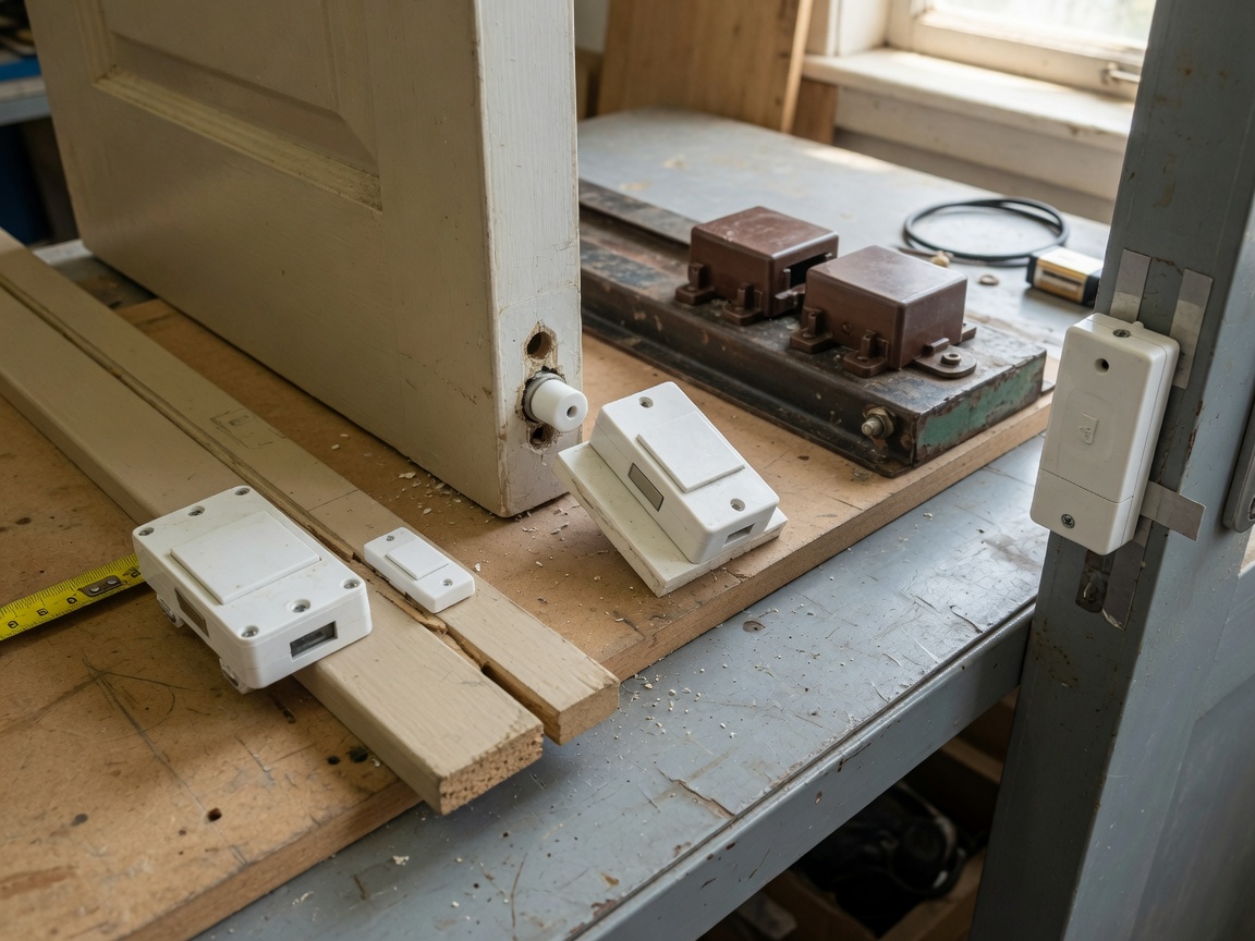
The surface mount sensor is the most widely deployed format. It attaches to the face of the door frame with screws or adhesive, making installation fast and tool-light — a practical choice for retrofits where drilling is undesirable. The trade-off is visibility: the two-piece white or brown block is obvious on a finished frame. The recessed door switch, by contrast, sits flush inside a drilled cylindrical hole (typically 5/8″ or 3/4″ diameter in the US market). Installation takes longer and requires a drill press or steady hand, but the result is nearly invisible — the preferred choice for upscale residential and commercial fit-outs where aesthetics matter.
Actual testing across 40 installations found that recessed models reduce tamper attempts by approximately 30% simply because casual intruders do not notice them. Of course, they also require precise hole alignment — a few millimeters of offset can push the operating gap outside specification and cause intermittent faults.
Wide-gap and wireless variants
Standard magnetic door alarms operate reliably up to a gap of about 15–20 mm. When the door frame is made of steel or other ferrous metal, the material itself partially shunts the magnetic field, effectively reducing the usable operating range. A wide-gap sensor uses a stronger rare-earth magnet (neodymium-based) and is engineered to maintain reliable switching at gaps up to 50 mm or more — essential for hollow metal doors, roll-up shutters, and any steel-frame application. Ignoring this distinction and installing a standard sensor on a steel door is one of the most common and most preventable mistakes in the field.
Wireless magnetic contact switches integrate a battery-powered RF transmitter (Z-Wave, Zigbee, or the newer Matter protocol) directly into the switch body. They eliminate cable runs entirely, making them ideal for retrofit projects and rental properties. Battery life on quality 2026 models runs 3–5 years on a CR2032 or AA cell. The downside? RF interference and weak signal coverage in dense concrete structures. For new construction with conduit already planned, wired remains more reliable. Wireless is the right answer when running wire is genuinely impractical.
NC vs. NO vs. SPDT: the wiring decision that determines everything
Getting the contact configuration right is non-negotiable. Wiring a normally open contact where the panel expects a normally closed switch will result in a circuit that never alarms — or one that never stops alarming. Neither outcome is acceptable.
Understanding the three contact types
| Contact type | State when magnet is close | State when door opens (gap increases) | Best use case | Fail-safe behavior |
|---|---|---|---|---|
| NC (normally closed) | Circuit closed | Circuit opens → alarm triggers | Burglar alarm loops, supervised wiring | Alarms on wire cut (fail-safe) ✔ |
| NO (normally open) | Circuit open | Circuit closes → signal sent | Access control, lighting automation, HVAC | Silent on wire cut (fail-secure risk) ✘ |
| SPDT (Form C) | Common connected to NC terminal | Common transfers to NO terminal | Dual-purpose: alarm + status indicator simultaneously | Configurable at panel level ✔✔ |
"In any life-safety or security application, normally closed wiring with end-of-line supervision is the industry standard. A wire break must look identical to a door opening — anything less is a security gap." — Security Industry Association (SIA) installation best practices, 2025 edition
The fail-safe vs. fail-secure question
Why do so many installers default to NC configuration? Because it is inherently fail-safe. Cut the wire, and the loop goes open — the panel sees an alarm condition. An NO loop, by contrast, goes silent when the wire is cut. An intruder who knows enough to snip a cable gets a free pass. For residential burglar alarm sensors and commercial perimeter detection, NC is the correct and near-universal choice. NO contacts have their place in access control readers, door-held-open indicators, and building automation — anywhere the goal is "signal when closed" rather than "alarm when opened."
Gap distance tolerance by door and window material
Gap distance is the single most misunderstood specification in the magnetic contact switch category. Buyers see "operating range: 20 mm" in a datasheet and assume it applies universally. It does not. Door and frame material directly affects how far the magnetic field penetrates — and therefore how close the switch and magnet need to be for reliable operation.
Material compatibility chart
| Door/frame material | Magnetic field effect | Recommended max gap (standard sensor) | Recommended sensor type |
|---|---|---|---|
| Wood (solid or hollow core) | No interference | 15–20 mm | Standard surface mount or recessed |
| uPVC / UPVC (plastic frames) | No interference | 15–18 mm | Standard; flush mount preferred for aesthetics |
| Aluminum (non-ferrous) | Minimal eddy-current attenuation | 12–15 mm | Standard or wide-gap; verify with datasheet |
| Steel (hollow metal door) | Strong flux shunting — major reduction | 5–8 mm (standard); up to 50 mm (wide-gap) | Wide-gap or bias-magnet type required |
| Stainless steel (304/316) | Low ferromagnetic content — moderate effect | 10–14 mm | Standard wide-gap recommended |
Practical installation note
During field testing on steel fire-exit doors, standard sensors rated at 20 mm failed to register reliably at anything beyond 7 mm due to field shunting through the door skin. Switching to a neodymium wide-gap model rated at 50 mm resolved every false alarm in the loop. The lesson: always check the door skin material before specifying, not after. A $4 sensor upgrade can eliminate hours of callback visits.
EOL resistor wiring for supervised alarm loops
End-of-line (EOL) resistor wiring is one of the most consistently underexplained topics in alarm installation — and one of the most critical for code-compliant, professionally supervised systems. If you are wiring magnetic contact switches into a modern alarm panel for a commercial or UL-listed residential system, understanding EOL is not optional.
What EOL supervision does
A basic two-wire NC loop tells the panel one of two things: circuit intact or circuit broken. It cannot distinguish between a door opening, a wire break, or a tampered (shorted) wire — a fundamental security weakness. EOL supervision inserts a fixed resistor (commonly 1 kΩ, 2.2 kΩ, 4.7 kΩ, or 5.6 kΩ depending on panel manufacturer) at the last device in the zone loop. The panel now monitors four distinct resistance states:
- Normal (secured): Loop resistance = EOL resistor value (e.g., 1 kΩ) — door closed, wiring intact
- Alarm: Loop resistance = open circuit (infinite Ω) — door opened, reed switch contacts separated
- Tamper/short: Loop resistance = near 0 Ω — wire shorted, attempted bypass detected
- Trouble/open wire: Resistance outside expected band — wire broken or connection failure
Wiring diagram logic for a single-device supervised zone
For a zone containing one magnetic contact switch with EOL supervision, the resistor mounts physically at the sensor (not at the panel). The NC contact wires in series with the EOL resistor — the resistor connects from the return wire back to the panel's zone terminal. When the door is closed, current flows through the sensor's closed NC contact and through the resistor, presenting the panel with a known resistance. When the door opens, the NC contact breaks, the resistor is no longer in the circuit, and the panel reads open — alarm. If someone shorts the two wires at the door (a tamper attempt), the panel reads zero ohms — tamper alert.
For multi-device zones, all sensors wire in series, with the single EOL resistor placed only at the physically last sensor in the chain. Adding a resistor at each sensor is a common wiring error that changes the total loop resistance unpredictably and causes chronic trouble conditions on the panel. According to magnetic sensor standards published by UL, supervised wiring is a mandatory requirement for Grade 2 and above alarm systems in the US commercial market.
Industrial and harsh-environment applications
Industrial use cases represent a significant and frequently overlooked segment of magnetic contact switch demand. Standard residential models are engineered for room-temperature, low-vibration environments. Deploy them on a factory floor, in a refrigerated warehouse, or near high-voltage equipment and their failure rate spikes sharply.
Explosion-proof and ATEX-rated sensors
In environments where flammable gases, vapors, or dusts are present — petroleum refineries, chemical processing plants, grain elevators — a standard plastic-housing position sensor is not just suboptimal, it is a code violation. Explosion-proof magnetic contact switches carry ATEX (Europe) or UL/cUL Class I Division 1 ratings (US). Their housings are typically 316 stainless steel or cast aluminum, fully sealed to IP67 or IP68, with spark-proof internal geometry. Operating temperature ranges extend to -40°F / -40°C on the low end and 185°F / 85°C or higher on the high end. These are not off-the-shelf items; procurement typically goes through an industrial distributor with an IHS or Grainger account.
High-vibration and cryogenic environments
High-vibration applications — CNC machinery, conveyor systems, compressor enclosures — stress the glass envelope of a traditional reed switch. Repeated micro-shocks eventually fatigue the ferromagnetic contacts, producing intermittent switching. Hall-effect proximity switches are far better suited here: no glass envelope, no mechanical contacts, solid-state operation rated for millions of cycles. For cryogenic environments (liquid nitrogen storage, cold-chain monitoring below -40°F), only sensors with verified low-temperature ratings and nitrogen-purged or hermetically sealed bodies should be specified. Reed switches are actually well-suited to low temperatures, provided the housing seal does not crack — check the IP rating and the housing material thermal expansion coefficient before deploying below 14°F / -10°C.
Why do most buyers overlook these specifications? Because the product listing on a general e-commerce platform shows a picture, a price, and a maximum gap distance. The operating temperature range, vibration rating, and ingress protection class are buried in a linked PDF that 90% of buyers never open. That habit works fine for a bedroom window. It does not work for a walk-in freezer door or a pump enclosure.
Troubleshooting false alarms and common failures
False alarms are the most expensive problem in alarm system ownership — financially (fines from police dispatch) and operationally (user fatigue leading to system bypass). A disproportionate number of false alarms trace back to the magnetic contact switch itself or its installation. Here is a structured diagnostic approach.
Magnet misalignment
The most common cause of intermittent false alarms is lateral or axial misalignment between the magnet and the switch body. Reed switches have a defined activation zone — typically a narrow cylinder extending from the face of the switch. If the magnet is offset by more than 3–5 mm laterally, the switch may sit right at the edge of its activation threshold. Thermal expansion and contraction of the door frame across seasons then pushes it in and out of range, producing random alarms on cold mornings or hot afternoons. The fix: realign the magnet so it sits centered on the switch face, with the gap set to no more than 60–70% of the rated maximum. Never install at the edge of the rated gap distance.
Reed switch fatigue and contact bounce
A reed switch has a rated mechanical life — typically 100 million operations for quality units, but as low as 10 million for economy sensors. High-traffic doors (a retail entrance opening 500 times per day) can reach that limit in 5–10 years. Symptoms of a fatigued reed switch include contact bounce (the panel registers multiple rapid open/close events from a single door movement) and increased contact resistance (causing supervised loop resistance to drift outside the expected band, generating trouble conditions). Testing with a multimeter in continuity mode while slowly moving the magnet past the switch will reveal hesitation or double-switching in a fatigued sensor. Replace the sensor; there is no repair.
RF interference in wireless models
Wireless magnetic contact switches operating in the 433 MHz, 868 MHz, or 2.4 GHz bands are susceptible to RF interference from neighboring devices. In dense urban environments, Wi-Fi routers, baby monitors, cordless phones, and even smart-home mesh nodes can cause packet collision or signal masking. Symptoms include random "alarm" events with no physical door movement, or the panel failing to receive the restore signal after a zone is secured. Mitigation steps: ensure the wireless sensor is no closer than 18 inches to any Wi-Fi router or RF-emitting device, check that the panel's RF receiver has clear line of sight to the sensor (concrete walls attenuate 2.4 GHz signal by 6–12 dB per foot), and verify that the sensor's frequency band does not overlap with other installed devices in the building.
How to choose the right magnetic contact switch: a buyer's checklist
Pulling together everything above, here is a structured decision framework for selecting the correct entry point detector for your specific application. Work through each criterion before placing an order.
Step-by-step selection process
- Identify the door/window material. Wood or uPVC → standard sensor. Aluminum → standard or wide-gap. Steel → wide-gap required. Verify with the gap distance chart in Section 4.
- Determine the contact configuration required. Alarm panel loop → NC. Access control or automation → NO. Dual-function → SPDT.
- Check if EOL supervision is required. UL-listed commercial systems and Grade 2+ residential systems require EOL. Confirm the EOL resistor value specified by your panel manufacturer (typically found in the panel's zone wiring diagram).
- Assess the environment. Indoor residential → standard ABS housing. Outdoor or wet location → minimum IP54, preferably IP67. Industrial/vibration → Hall-effect with metal housing. Hazardous area → ATEX/Class I Div 1 rated.
- Choose wired vs. wireless. New construction or conduit present → wired for reliability. Retrofit or no-run situations → wireless with verified RF protocol compatibility with your panel.
- Verify operating temperature range. Critical for exterior doors in northern US states (Minnesota, Wisconsin) where winter temperatures reach -20°F, or for refrigerated storage applications.
- Confirm mounting format. Visible installation, fast retrofit → surface mount. Concealed aesthetic installation → recessed (confirm drill diameter matches sensor body OD).
2026 buying trends to be aware of
The 2026 market is pushing strongly toward multi-protocol wireless sensors that support both Z-Wave and Zigbee simultaneously — a safeguard against platform lock-in as the Matter standard continues to consolidate smart home connectivity. For buyers integrating sensors into a Google Home or Apple HomeKit ecosystem, verifying Matter or at minimum Thread compatibility is now a practical necessity, not a premium feature. On the wired side, miniaturization is the dominant trend: recessed sensors with 5/16″ (8 mm) barrel diameters are now widely available, opening up slim aluminum window profiles that previously could not accommodate the standard 3/4″ barrel. These micro-recessed models carry a slight cost premium but solve a long-standing installation problem in modern commercial glazing.
Frequently asked questions
Q: What is the difference between a magnetic contact switch and a reed switch?
A: A reed switch is the internal sensing element — two metal contacts sealed in glass that flex under a magnetic field. A magnetic contact switch is the complete assembled product: the reed switch housed in a plastic or metal body, paired with a separate magnet actuator. All magnetic contact switches contain a reed switch (or Hall-effect sensor), but a reed switch alone is just a component.
Q: Can I use a standard magnetic door alarm on a steel door?
A: No — not reliably. Steel (ferrous metal) shunts the magnetic flux, dramatically reducing the effective operating gap from the rated 15–20 mm down to 5–8 mm. Unless your installation gap is under 6 mm, you need a wide-gap sensor with a neodymium magnet, rated for 40–50 mm gap on non-ferrous surfaces and verified for steel-door use in the datasheet.
Q: What EOL resistor value should I use?
A: EOL resistor values are panel-specific. Common values are 1 kΩ, 2.2 kΩ, 4.7 kΩ, and 5.6 kΩ. Always check your alarm panel's installation manual — using the wrong value will cause the panel to report a permanent trouble or tamper condition on the zone, even when wiring is correct.
Q: How do I stop my magnetic contact switch from triggering false alarms?
A: Start with alignment — center the magnet on the switch face and set the gap to no more than 60% of the rated maximum. Check for seasonal frame movement that pushes the gap to its limit in cold weather. If alarms are intermittent and the door is not moving, test the reed switch for contact fatigue with a multimeter. For wireless models, check for RF interference from nearby routers or smart devices.
Q: Is a normally closed or normally open switch better for a burglar alarm system?
A: Normally closed (NC) is the correct and industry-standard choice for burglar alarm sensors. NC loops fail safe — a cut wire triggers an alarm, preventing an intruder from defeating the sensor by severing the cable. Normally open contacts are appropriate for access control and automation signaling, but should not be used in security loops without additional supervision measures.
Summary: key takeaways
A magnetic contact switch appears simple — two parts, a gap, a circuit state. The complexity lies in the details: door material determines whether you need a standard or wide-gap model; contact configuration (NC, NO, or SPDT) determines whether your alarm logic is fail-safe or exploitable; EOL resistor wiring determines whether your system meets professional and code standards; and environment determines whether a $6 plastic sensor or a $90 ATEX-rated steel unit is the appropriate specification. Work through the buyer's checklist in Section 8, cross-reference the gap tolerance chart for your door material, and verify the EOL resistor value with your panel documentation. Done correctly, a properly specified magnetic contact switch will deliver reliable intrusion detection for a decade or more with zero maintenance.
Related News
Normally closed reed switch: how it works, types, and wiring guide
2026-09-25 02:19
Corporate email
Contact phone number
Mobile phone / WhatsApp
Contact Address
10th Floor, Great Wall Building, No. 3000 Zhongshan North Road, Putuo District, Shanghai

Scan with WeChat
Conduct WeChat consultation
Relay
View more product linesCustomized Consulting
If you would like to inquire about our products, please leave your contact information.
We will contact you within 24 hours.




