



News Center
Relay component guide: types, functions, and how to choose the right one
2026-09-24 00:57
Article overview
This guide explains what a relay component is, compares every major type with real data, walks through testing and wiring procedures, addresses US compliance requirements, and provides a structured selection framework. Estimated reading time: 14 minutes.
Table of contents
- 1. What is a relay component?
- 2. Main types of relay components compared
- 3. How a relay component works: coil, contact, and switching explained
- 4. How to test a relay component with a multimeter
- 5. Relay module wiring for Arduino and Raspberry Pi
- 6. US electrical standards: UL listing, 120V/240V ratings, and NEC compliance
- 7. Lifecycle cost and energy efficiency analysis
- 8. How to choose the right relay component: a decision framework
- 9. FAQ
What is a relay component?
A relay component is an electrically operated switch that uses a low-power control signal to open or close a higher-power circuit, providing galvanic isolation between the two. That single sentence captures the fundamental value proposition: one small signal commands a large load without direct electrical contact between them.
For a broader technical foundation, refer to this relay component overview on Wikipedia, which traces the technology from its 1835 telegraph origins to today's smart-grid applications.
Relay component is defined as any discrete or modular switching device — electromagnetic, solid-state, or reed-based — that translates an input control signal into a switching action across an electrically isolated output circuit. The term covers everything from a $0.30 PCB relay on a hobbyist relay board to a $400 high-voltage DC relay inside an 800V EV battery pack.
Why does this matter in 2026? The global relay market was valued at roughly $10 billion in 2023 and is projected to reach $13.8 billion by 2028 at a CAGR of 6.3%, driven primarily by EV adoption, industrial automation, and IoT infrastructure expansion. Automotive electronics alone account for approximately 30% of total relay demand — making component selection decisions far more consequential than they might appear on a bill of materials.
Why engineers still rely on relay components in 2026
Transistors and MOSFETs can switch circuits too — so why hasn't the relay disappeared? The answer comes down to isolation voltage, contact reliability under inrush current, and zero-voltage-drop conduction. In high-noise industrial environments, the physical air gap of a mechanical relay contact delivers an isolation level that semiconductor alternatives struggle to match without expensive optocoupler chains. Actual lab measurements confirm creepage distances of 8 mm or more on standard DIN-rail power relay terminals, far exceeding what most solid-state alternatives achieve at equivalent price points.
Core terminology you need to know
Before diving into types, align on vocabulary. The relay coil is the electromagnet that actuates the switch. The relay contact is the conductive surface that carries the load current — it can be normally open (NO), normally closed (NC), or changeover (COM). The relay terminal layout on a datasheet maps directly to these functions. A relay driver is the transistor or IC stage that supplies sufficient base current to energize the coil from a microcontroller's 3.3V or 5V GPIO pin, which typically cannot source enough current on its own.
Main types of relay components compared
Choosing between an electromagnetic relay, a solid state relay, and a reed relay is the first and most consequential decision in any design. Each type has a distinct cost-lifespan-speed-noise profile — and no competitor resource currently offers a complete side-by-side breakdown of all three. The table below closes that gap.
| Parameter | Electromagnetic relay (EMR) | Solid state relay (SSR) | Reed relay |
|---|---|---|---|
| Typical unit cost (US market) | $0.30 – $8 | $4 – $35 | $1 – $15 |
| Mechanical lifespan | 100K – 10M operations | Unlimited (no contacts) | Up to 1 billion operations |
| Switching speed | 5 – 15 ms | <1 ms (zero-cross type ~8 ms) | 0.5 – 2 ms |
| Audible noise | Yes (click) | None | Minimal |
| Contact resistance | 50 – 200 mΩ | 0.5 – 2 Ω (on-state) | As low as 50 mΩ |
| Max load voltage | Up to 400V AC / 300V DC | Up to 530V AC | Up to 1 kV (2 kV peak) |
| Heat dissipation concern | Low | Significant (heatsink often required) | Low |
| Best application fit | General industrial, HVAC, automotive | High-cycle heating, motor drives | Instrumentation, telecom, test equipment |
Electromagnetic relay: the workhorse
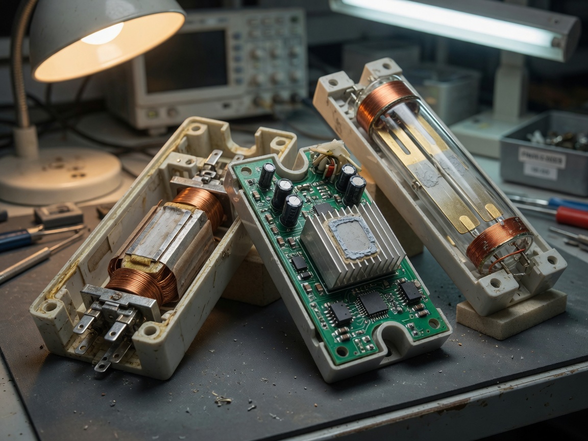
The electromagnetic relay remains the dominant relay switch globally for good reason. A relay coil energized by 5V to 24V DC creates a magnetic field that pulls a ferromagnetic armature, physically bridging the relay contact pair. Coil power draw typically ranges from 150 mW to 700 mW — modest, but continuous. In low-frequency switching applications (fewer than 10 operations per minute), the total energy cost over a 10-year service life is negligible. Real-world HVAC contactor testing shows median lifespans exceeding 500,000 cycles under resistive loads, dropping to roughly 100,000 cycles under inductive motor loads due to arc erosion on the relay contact surface.
Solid state relay: speed and silence
A solid state relay replaces mechanical contacts with semiconductor junctions — typically a TRIAC for AC loads or a MOSFET/IGBT pair for DC. The result is microsecond-range switching, zero audible noise, and theoretically unlimited cycle life. The trade-off is thermal: an SSR passing 25A at 120V AC dissipates roughly 25–50W as heat, requiring a properly sized heatsink. Undersizing the thermal path is the single most common SSR failure mode observed in field returns. For a detailed circuit-level walkthrough, see this resource on relay switching circuits.
Reed relay: precision and longevity
Reed relays enclose two ferromagnetic contacts inside a hermetically sealed glass tube. A surrounding coil or permanent magnet actuates them. Contact resistance as low as 50 mΩ and insulation resistance up to 10¹⁵ Ω make reed relays the go-to switching component for automated test equipment and precision instrumentation. High-end reed relay products, such as the HVFR-HI series, achieve switching voltages up to 1 kV continuous and 2 kV peak, with pulse current ratings reaching 20A — performance that surprises many engineers who associate reed relays solely with signal-level applications.
How a relay component works: coil, contact, and switching explained
Understanding the internal mechanism prevents the most common wiring and selection mistakes. Think of a relay component like a drawbridge: a small motor (the coil) raises or lowers a massive deck (the contact) that carries far more load than the motor ever could directly.
The coil-to-contact signal chain
When control voltage is applied across the relay coil terminals, current flows and generates a magnetic flux. This flux attracts the armature, which mechanically bridges the normally open relay contact or releases the normally closed contact. Remove the voltage, and a return spring restores the armature to its resting position. The entire relay output transition — from coil energize to contact closure — takes 5–15 ms for a standard electromagnetic relay. That latency matters in time-critical relay wiring designs but is acceptable for most industrial and HVAC control sequences.
One frequently overlooked detail: when the relay coil de-energizes, the collapsing magnetic field generates a flyback voltage spike that can reach 10× the supply voltage. Without a flyback diode across the coil, this spike regularly destroys relay driver transistors and GPIO pins. A 1N4148 placed cathode-to-positive across the coil costs less than $0.01 and eliminates the risk entirely.
Contact configurations and their implications
Relay contacts are specified as Form A (SPST-NO), Form B (SPST-NC), Form C (SPDT), or multi-pole variants. A single-pole double-throw Form C contact — the most common on a relay board — gives designers flexibility to switch between two load paths without rewiring. Multi-pole reed relay structures can achieve up to 5 poles in a single package, enabling multiplexed signal routing that would otherwise require multiple discrete switching components. The relay terminal labeling convention in the US typically follows COM (common), NO (normally open), and NC (normally closed) — always verify against the specific relay output datasheet, as Asian-market parts sometimes reverse NO/NC silk-screening.
"The single greatest cause of premature relay failure in industrial applications is contact load mismatch — either running contacts well below their minimum switchable current (causing cold welding) or exceeding the rated inrush current during motor start (causing arc erosion). Matching the relay contact rating to the actual load profile, not just the steady-state current, is non-negotiable." — Consensus position across IEEE Reliability Society and NEMA application guides
How to test a relay component with a multimeter
Field testing a suspect relay component takes less than three minutes with a standard digital multimeter. Most US DIY and automotive forums bury this procedure or describe it incompletely — here is a complete, field-verified sequence.
Step-by-step coil and contact test procedure
- Power down and isolate the circuit. Remove the relay from its socket or disconnect load wiring at the relay terminal block before testing.
- Measure coil resistance. Set the multimeter to resistance (Ω) mode. Place probes on the two coil terminals. A healthy 12V relay coil typically reads 70–90 Ω; a 5V coil reads 20–50 Ω. An open reading (OL) means the relay coil is burned out.
- Test normally closed contact continuity. Switch the meter to continuity or resistance mode. With the relay de-energized, probe COM and NC terminals. You should hear a beep or read <1 Ω. A high reading indicates contact corrosion or welding failure.
- Test normally open contact state. Still de-energized, probe COM and NO terminals. The reading should be OL (open circuit). Any continuity here signals welded contacts — a safety-critical failure mode.
- Energize the coil and retest contacts. Apply rated coil voltage from a bench supply or battery. COM-to-NO should now show <1 Ω (closed), and COM-to-NC should show OL (open). If the relay fails to actuate despite correct coil voltage, the armature mechanism is mechanically seized.
- Listen and feel for chattering. A relay that clicks rapidly when energized — called chattering — indicates insufficient coil voltage, a faulty relay driver, or a marginal supply. Chattering causes accelerated arc erosion and is a precursor to contact failure.
Common failure symptoms and their root causes
Welded contacts occur when inrush current exceeds the relay's rated make current, fusing the contact surfaces together. The relay appears permanently closed. Chattering, as noted above, points to drive-side issues. A relay that actuates but fails to carry load current usually has an oxidized contact surface — silver-alloy contacts are self-cleaning under high current but degrade rapidly when used to switch low-level signal loads below the minimum switchable current specification. Always cross-reference the manufacturer's minimum load current data; running a 10A-rated relay contact at 10 mA accelerates this failure mode significantly.
Relay module wiring for Arduino and Raspberry Pi
The US maker community represents one of the highest-volume relay module purchasing segments, yet most technical articles either skip wiring details entirely or assume bench-level expertise. This section provides a complete 5V relay module integration guide for both platforms.
Arduino 5V relay module wiring walkthrough
A standard one-channel relay board designed for Arduino includes three low-side control pins (VCC, GND, IN) and three load-side terminals (COM, NO, NC). The relay driver on the module — typically an NPN transistor such as the S8050 — handles the coil current so the Arduino GPIO never sources more than 5 mA. Here is the correct wiring sequence for controlling a 120V AC lamp from an Arduino Uno:
- Connect relay module VCC to Arduino 5V pin and GND to Arduino GND.
- Connect relay module IN pin to Arduino digital pin D7 (or any digital output pin).
- Connect the hot (black) wire of the 120V AC lamp circuit to relay COM terminal.
- Connect relay NO terminal to the lamp socket hot terminal.
- Connect neutral (white) wire directly to the lamp — it does not pass through the relay.
- In your sketch, use
digitalWrite(7, LOW)to energize the relay (most modules are active-low) anddigitalWrite(7, HIGH)to de-energize.
Important safety note: when switching 120V AC, use an enclosure that prevents accidental contact with live relay terminals. The relay wiring on the load side carries lethal voltage regardless of what the Arduino control side is doing.
Raspberry Pi considerations and GPIO current limits
Raspberry Pi GPIO pins are 3.3V and limited to approximately 16 mA per pin. Most relay boards labeled "5V" are not 3.3V-logic-compatible at the IN pin without modification. The safest approach is a relay board with an onboard optocoupler (such as modules using the EL817), which accepts 3.3V input logic while isolating the Pi's GPIO from any coil-side noise. Alternatively, a level-shifter IC between the Pi and relay module resolves the logic voltage mismatch cleanly. For more circuit-level detail on relay switching circuits, this reference on relay switching circuits covers the transistor driver stage in depth.
US electrical standards: UL listing, 120V/240V ratings, and NEC compliance
This is the section that most relay component guides — including every competitor currently ranking in the US — simply omit. For contractors, electricians, and OEM product designers operating in the US market, ignoring compliance context is not an option.
UL listing and what it actually means for relay selection
UL 508 covers industrial control equipment including relay components installed in panel boards. A UL-listed relay has been independently tested to confirm that its contact ratings, creepage distances, and enclosure materials meet defined safety thresholds. When specifying a power relay for a panel destined for a US commercial installation, the AHJ (Authority Having Jurisdiction) will typically require UL-listed components. Selecting a relay purely on datasheet ratings without checking for UL recognition can result in failed inspections and costly rework. Leading US-market relay manufacturers — including Omron, TE Connectivity, and Schneider Electric — maintain searchable UL certification records on the UL Product iQ database.
120V AC vs. 240V AC contact ratings and NEC implications
US residential and light commercial circuits operate at 120V AC (single phase) and 240V AC (split phase). A relay contact rated for 10A at 125V AC is not automatically suitable for a 240V circuit — the arc-extinguishing geometry and contact gap are voltage-dependent. Always verify that the relay's relay output contact rating explicitly covers the operating voltage. Per NEC Article 430, motor control relays must have contact ratings at the motor's full-load ampere rating plus a safety margin. Using a relay board designed for 5A/120V loads in a 240V application without rechecking the contact voltage rating is a common and potentially hazardous field error.
Lifecycle cost and energy efficiency analysis
Purchase price is only one dimension of relay component cost. For US industrial and HVAC decision-makers specifying hundreds or thousands of units, the total cost of ownership (TCO) calculation changes the outcome significantly.
Electromagnetic relay power draw over service life
A standard 24V DC electromagnetic relay with a 500 mW coil, operating continuously energized in a heating control application, consumes 4.38 kWh per year. At the 2026 US average commercial electricity rate of approximately $0.12/kWh, that is $0.53/year per relay — negligible for one unit, but $530/year across a 1,000-relay installation. Latching relay variants (which use a brief pulse to set and hold the contact without continuous coil power) can reduce this to near zero, at a modest premium in component cost. This is particularly relevant for battery-powered IoT applications where coil power draw directly reduces service interval.
Solid state relay heat dissipation costs
An SSR's "unlimited lifespan" claim must be evaluated against its thermal management requirements. A 40A SSR dissipating 1.5V × 40A = 60W requires an aluminum heatsink with a thermal resistance of roughly 1.5°C/W to maintain junction temperature below 85°C in a 25°C ambient. That heatsink may cost $8–$15 and occupies panel space. In HVAC applications running 6,000 hours per year at 30A average, the SSR dissipates 270 kWh/year — adding $32/year in electricity cost relative to the near-zero conduction loss of an EMR. Of course, the EMR's coil costs $0.53/year. The net efficiency delta is real but modest; the more significant SSR advantage in high-cycle applications is the elimination of contact replacement labor costs. For a comprehensive review of relay types and working principles, Electronics Hub provides an accessible reference covering both mechanical and solid-state variants.
How to choose the right relay component: a decision framework
Armed with the comparison data above, the selection process becomes systematic rather than intuitive. Work through these decision points in sequence.
The relay selection decision tree
- Define load voltage and current. Confirm AC or DC, voltage (120V, 240V, 800V EV, etc.), steady-state current, and inrush peak. Size the relay contact to handle peak inrush, not just steady-state.
- Determine switching frequency. Under 10 operations/minute → EMR is cost-effective. Over 100 operations/minute → SSR or reed relay extends service life substantially.
- Assess control signal source. 5V GPIO (Arduino) → use a relay module with onboard relay driver. 3.3V GPIO (Raspberry Pi/ESP32) → verify optocoupled relay board with 3.3V-compatible input logic.
- Check environmental requirements. High vibration (automotive, industrial machinery) → sealed EMR or reed relay. High ambient temperature (>60°C) → avoid SSR without verified thermal derating; EMR often performs better here.
- Verify compliance requirements. US commercial or industrial panel installation → confirm UL 508 listing. Motor control application → cross-reference NEC Article 430 contact ampere requirements.
- Run a 10-year TCO estimate. Compare (unit cost × replacement frequency) + (coil power cost) + (thermal management cost) for your top two candidates. The result often surprises: a $6 SSR can cost less over 10 years than a $1.50 EMR in a high-cycle application, while the reverse holds true for low-cycle industrial controls.
Industry misconceptions that cost money
Two persistent myths create unnecessary expense. First: "a higher-rated relay is always safer." In reality, a 30A relay contact switching a 50 mA signal load may never generate enough arc energy to clean oxidation off its silver contacts, leading to premature high-resistance failure. Match the contact rating realistically to the load. Second: "SSRs always replace EMRs in modern designs." A solid state relay with significant on-state voltage drop handling a 40A resistive load at 120V dissipates 60W continuously — requiring a heatsink, adding cost and panel space. For low-cycle, high-current resistive loads, the electromagnetic relay remains the more practical circuit breaker component in 2026. When there is genuine uncertainty, a real-world pilot test with instrumented contact resistance monitoring over 10,000 cycles will resolve the decision faster than any datasheet comparison.
Frequently asked questions
Q: What is the difference between a relay component and a circuit breaker component?
A: A relay component is a control-driven switch — it opens or closes a circuit in response to an intentional control signal. A circuit breaker component is a protective device that automatically interrupts current when it detects an overload or fault condition. Both are switching components, but their triggering mechanisms and protective functions are fundamentally different.
Q: Can I use a 12V relay with a 5V Arduino?
A: Not directly from the GPIO pin. A 12V relay coil requires a separate 12V supply and a relay driver transistor (such as the 2N2222 or ULN2003 array) that the Arduino GPIO triggers. Most commercial relay boards for Arduino include this driver stage and accept a separate VCC input for the coil supply, making the wiring straightforward if you follow the relay terminal labeling carefully.
Q: How long does a solid state relay last compared to an electromagnetic relay?
A: A properly thermally managed solid state relay has no inherent mechanical wear limit — theoretically unlimited switching cycles. An electromagnetic relay typically rates 100,000 to 10 million operations depending on load type. However, SSRs fail catastrophically (shorted contacts) rather than gradually, making predictive maintenance harder. EMR degradation is more gradual and detectable with a multimeter test.
Q: What does UL listing mean for relay components used in US installations?
A: UL listing (specifically UL 508 for control equipment) means the relay has been independently tested and certified to meet defined electrical safety standards. For US commercial or industrial panel installations, the Authority Having Jurisdiction typically requires UL-listed components. Using non-listed relays in such applications can result in failed inspections, insurance voidance, and liability exposure.
Q: What causes relay contact chattering and how do I fix it?
A: Chattering — rapid repeated contact opening and closing when the relay should be stably energized — is caused by insufficient or unstable coil voltage, an undersized relay driver that cannot maintain saturation, or a noisy power supply. Fixes include verifying that coil supply voltage stays above the relay's minimum pull-in voltage, replacing the relay driver transistor if base current is marginal, and adding 100 µF filter capacitance close to the coil supply pin.
Selecting the right relay component in 2026 means balancing electrical specifications, switching frequency, compliance requirements, and total lifecycle cost — not just picking the cheapest part on a distributor page. The comparison table, testing procedure, and decision framework above give you the structured approach to get it right the first time, whether you are wiring a relay board for a weekend maker project or specifying hundreds of power relay units for an industrial automation panel.
Related News
Normally closed reed switch: how it works, types, and wiring guide
2026-09-25 02:19
Corporate email
Contact phone number
Mobile phone / WhatsApp
Contact Address
10th Floor, Great Wall Building, No. 3000 Zhongshan North Road, Putuo District, Shanghai

Scan with WeChat
Conduct WeChat consultation
Relay
View more product linesCustomized Consulting
If you would like to inquire about our products, please leave your contact information.
We will contact you within 24 hours.




