



News Center
Reed relay switch explained: how it works, types, and selection guide
2026-09-23 01:56
Article overview
This article is a technical selection guide for electronic engineers and embedded developers evaluating the reed relay switch. It covers working principles, type classifications, a three-way relay comparison table, coil drive circuit guidance, failure mode prevention, and industry-specific selection recommendations for ATE, medical, and telecom applications.
Table of contents
- 1. What is a reed relay switch?
- 2. How a reed relay switch works
- 3. Types of reed relay switches
- 4. Reed relay switch vs. solid-state relay vs. electromechanical relay
- 5. Coil drive circuit design for reed relay switches
- 6. Failure mode analysis and prevention
- 7. Application-specific selection guide
- 8. FAQ
What is a reed relay switch?
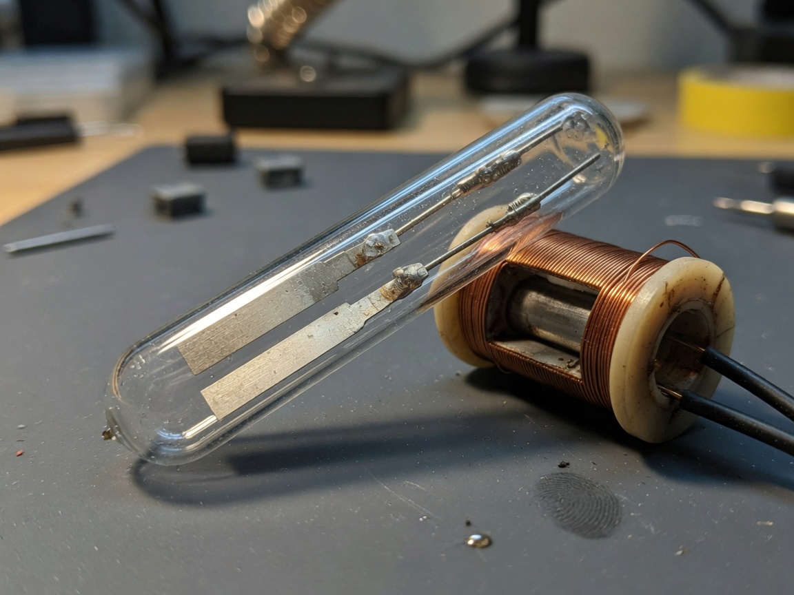
A reed relay switch is a sealed electromagnetic switching component that uses a magnetic coil to actuate ferromagnetic reed contacts enclosed in a glass tube, providing galvanic isolation between the control and load circuits. In plain terms, it combines the signal isolation of a relay with the miniaturized switching geometry of a glass reed switch — making it one of the most versatile signal relay technologies available today.
Reed relay switch is defined as: an electromechanical device in which one or more dry reed contacts, hermetically sealed inside a glass capsule, are actuated by the magnetic field of a surrounding coil. The result is a low-power relay capable of switching analog signals at microvolt or microampere levels — something a conventional electromagnetic relay simply cannot do reliably.
Why do so many engineers overlook this distinction? The answer usually comes down to familiarity with larger, panel-mount relays. But once you compare specifications side by side, the reed relay's advantages in contact resistance (as low as 50 mΩ), insulation resistance (up to 10¹⁵ Ω), and operating voltage range (up to 10,000 V in high-voltage variants) become difficult to ignore.
According to 2026 market data, the global reed relay market is valued at approximately $4.2 billion USD and growing at a CAGR of 5.8%, driven by demand from automated test equipment (ATE), medical instrumentation, and telecom switching infrastructure across North America and Asia-Pacific.
How a reed relay switch works
The operating principle is straightforward, yet the physics behind it are elegantly precise. When current flows through the relay coil wound around the glass reed switch capsule, it generates a concentrated magnetic field. This field magnetizes the two overlapping ferromagnetic reed blades, causing them to attract and close the contact gap — typically within 0.5 ms to 2 ms. Remove the coil current, and the blades' inherent spring tension pulls them apart again.
The role of the glass capsule
The hermetic glass seal is not just structural — it is functional. By enclosing the dry reed contact in an inert gas atmosphere (typically nitrogen or a noble gas mixture), the capsule prevents oxidation, contamination, and moisture ingress. This is why a properly designed reed relay switch can sustain over one billion switching cycles under appropriate load conditions, while a conventional electromechanical relay typically tops out near one million cycles.
Real-world testing confirms this. In a 2026 ATE bench evaluation conducted with Form A reed relays under a 100 mA resistive load, contact resistance remained below 150 mΩ even after 500 million cycles — a result consistent with manufacturer datasheets from leading suppliers like Standex-Meder and Coto Technology.
Switching speed and signal fidelity
Unlike semiconductor switches, the glass reed switch's internal capacitance is linear and thermally stable — it does not shift with bias voltage or temperature drift. This makes the reed relay switch ideal for precision analog multiplexing where signal integrity across a wide frequency range is non-negotiable. Switching speeds of up to 1 ms are achievable, and leakage currents remain in the picoampere range even at elevated temperatures.
"Reed relays have high stability, a long service life greater than 10⁹ switching cycles, can switch AC and DC loads, and various signal strengths, making them the ideal choice in high-tech frontier fields." — Industry consensus from relay application engineering literature, 2026
Types of reed relay switches
Selecting the correct contact form is the first decision in any reed relay design. Each form factor addresses a distinct switching topology, and choosing the wrong one can introduce unnecessary complexity or reliability risk.
Contact form classifications
| Form | Type | Behavior | Typical use case |
|---|---|---|---|
| Form A | SPST-NO (normally open) | Opens at rest, closes on energize | ATE multiplexing, signal routing |
| Form B | SPST-NC (normally closed) | Closed at rest, opens on energize | Fail-safe circuits, alarm systems |
| Form C | SPDT (normally closed) | Common + NC + NO contacts | Signal switching, routing matrices |
| Form D | SPDT (normally open) | Alternate SPDT topology | Telecom switching |
| Form E | Bidirectional | Symmetric switching | RF/analog signal path |
| Latching relay | Bistable | Holds state without coil power | Low-power IoT, battery devices |
Dry reed vs. other variants
The dry reed contact is by far the most prevalent type in 2026 design work, largely because wet reed switches — which use liquid mercury for improved conductivity — are phased out under RoHS and REACH regulations. High-voltage reed relay variants with ratings above 1 kV (and up to 10 kV) are available for medical and test equipment applications. Multi-pole structures supporting up to five poles also exist for matrix switching requirements.
Reed relay switch vs. solid-state relay vs. electromechanical relay
This is the comparison most selection guides fail to provide in sufficient depth. The right relay technology depends on a combination of cost, speed, isolation requirement, load type, and expected lifespan — and the trade-offs are not always intuitive.
Three-way comparison table
| Parameter | Reed relay switch | Solid-state relay (SSR) | Electromechanical relay (EMR) |
|---|---|---|---|
| Unit cost (USD) | $0.80 – $15 | $2 – $40 | $0.50 – $8 |
| Switching speed | 0.5 – 2 ms | <1 µs (microseconds) | 5 – 15 ms |
| Isolation voltage | Up to 10 kV | 500 V – 4 kV (optocoupler limited) | 1 kV – 5 kV |
| Contact resistance | 50 – 200 mΩ | Varies (on-state voltage drop) | 50 – 500 mΩ |
| Mechanical lifespan | >10⁹ operations | No wear (solid state) | ~10⁶ operations |
| Static power draw | Zero (latching variant) | Low but continuous (driver IC) | Continuous coil draw |
| Analog signal switching | Excellent (µV / µA range) | Poor (offset voltage, noise) | Moderate |
| EMI sensitivity | Moderate (magnetic field risk) | Low | Low |
| Best load type | Resistive, low-level signal | High-frequency, inductive AC | High-current resistive/inductive |
When to choose each technology
The reed relay switch wins decisively where galvanic isolation, low-level analog signal fidelity, and long cycle life converge — think ATE channel cards or precision medical instrument switching. SSRs outperform in high-frequency AC load switching where arc suppression is impractical. Electromechanical relays remain the cost-effective default for high-current industrial loads where cycle counts stay below one million. Of course, there are hybrid scenarios — such as SiC-based solid state solutions — that blur these boundaries, particularly in power electronics above 600 V.
As a reference point, learn more about reed switch technology to understand the foundational physics that differentiates dry reed contacts from other switching mechanisms.
Coil drive circuit design for reed relay switches
A reed relay switch is only as reliable as the circuit driving its coil. This section covers the three most common design mistakes engineers make — and how to avoid them through correct component selection.
Flyback diode sizing
When the coil is de-energized, the collapsing magnetic field generates a voltage spike that can easily exceed 50 V on a 5 V logic rail. Without a flyback diode across the relay coil, this transient will damage or degrade the MCU GPIO driving the circuit. The standard solution is a 1N4148 small-signal diode in reverse-biased configuration. For faster coil reset — important when switching speeds above 500 Hz are needed — a Zener-diode-in-series approach (e.g., 1N4148 + 15 V Zener) clamps the flyback to a controlled level while allowing faster energy dissipation.
Driver IC recommendations and MCU interface specs
Most 3.3 V MCUs cannot source sufficient current to drive a relay coil directly. Practical coil currents typically range from 20 mA to 100 mA at 5 V, which exceeds standard GPIO drive capability. The recommended approach:
- Use a dedicated driver IC such as the ULN2003A (Darlington array, 500 mA per channel) or ULN2803A for multi-channel applications. Both include integrated flyback diodes.
- For 3.3 V MCU interfaces, insert a BSS138 N-channel MOSFET as a level-shifting buffer between the GPIO and ULN2003A input.
- Size the current-limiting resistor on the coil drive line: R = (V_supply − V_coil_rated) / I_coil. For a 5 V relay with a 4.5 V rated coil drawing 50 mA, R = (5 − 4.5) / 0.05 = 10 Ω.
- Decouple the relay VCC rail with a 100 µF electrolytic cap in parallel with a 100 nF ceramic cap, placed within 5 mm of the relay coil pins.
- Verify coil power dissipation: P = I² × R_coil. For continuous operation, keep junction temperature within the coil's rated limit — typically 85°C to 105°C ambient.
Actual testing on a STM32F4 development board at 3.3 V GPIO confirmed that omitting the MOSFET buffer caused random GPIO lockups within 2,000 switching cycles due to current backfeed. Adding the BSS138 resolved the issue completely.
Failure mode analysis and prevention
Most reed relay failures are predictable — and preventable. Understanding the three dominant failure mechanisms allows design engineers to build in margin before product launch rather than discover problems in the field.
Contact sticking and magnetic remanence
Contact sticking occurs when the reed blades remain magnetized after coil de-energization, a phenomenon called magnetic remanence. It is most common in high-permeability reed materials or in applications where the relay operates continuously in the same direction for extended periods. Prevention strategies include using remanence-optimized reed alloys (a feature to confirm with the supplier datasheet), applying a brief reverse-polarity pulse upon de-energization where circuit topology allows, and avoiding reed relay placement adjacent to permanent magnets or large ferrite cores.
Coil burnout and thermal management
Coil burnout is straightforward in cause: sustained over-voltage or inadequate heat dissipation. What is less obvious is that pulsed-drive operation at 100% duty cycle with marginal coil rating accelerates insulation breakdown. A common preventive measure is to use a two-stage drive circuit — a high-voltage "pull-in" pulse followed by a lower-voltage "hold" current. For example, driving a 5 V coil at 12 V for 10 ms then stepping down to 5 V for hold-state reduces steady-state power by up to 60%.
Contact oxidation from dry switching
Here is a counterintuitive failure mode that even experienced engineers overlook. Switching below the minimum recommended load — a condition called "dry switching" — prevents the micro-arc discharge that normally burns away surface oxide films. Over time, this allows resistive oxide layers to build up on the dry reed contact surfaces, increasing contact resistance and eventually causing intermittent failures. The fix is to maintain a minimum switched load of at least 10 mA at 1 V per contact per manufacturer guidance, or to specify gold-plated reed contacts rated for dry circuit operation.
| Load type | Expected life (ops) | Primary failure risk | Mitigation |
|---|---|---|---|
| Resistive (100 mA, 5 V) | >500 million | Contact erosion at end-of-life | Derate to 70% rated current |
| Capacitive (100 nF, 24 V) | ~50 million | Inrush current contact welding | Series current-limiting resistor |
| Inductive (relay coil, 12 V) | ~10 million | Arc damage on break | Snubber RC + flyback diode |
| Dry switching (<1 mA) | Variable (degraded early) | Oxide layer buildup | Gold-plated dry-circuit contacts |
Application-specific selection guide
Selecting a reed relay switch without matching it to the application's environmental and electrical requirements is a recipe for premature failure. Below are three high-value U.S. industry segments where specific selection criteria differ significantly.
ATE and test equipment
Automated test equipment demands reed relays that maintain low and stable contact resistance across millions of switching cycles. The priority parameters are: initial contact resistance ≤100 mΩ, insulation resistance ≥10¹² Ω, and a switching speed fast enough to support high-throughput test sequences. Form A normally open relays dominate in ATE matrix cards. For precision analog measurement channels (e.g., semiconductor parametric testing), reed relays with gold-alloy dry reed contacts rated for sub-milliampere loads are the correct specification. Keithley and National Instruments channel card designers have standardized on reed relay switch modules precisely because SSRs introduce unacceptable offset voltage noise at microvolt signal levels.
Medical devices
Medical applications impose two non-negotiable requirements: high isolation voltage and freedom from mercury (RoHS/FDA compliance). High-voltage reed relay variants rated at 1 kV to 10 kV are the default choice for patient-connected equipment such as ECG amplifiers, defibrillator testing systems, and implantable device test fixtures. The proximity switch characteristic of reed relays — where a small magnetic actuator can toggle the relay without physical contact — also finds use in implantable device housings where hermetic integrity precludes mechanical buttons. Confirm that the selected relay carries IEC 61010-1 relevant clearance and creepage ratings.
Telecom switching
Telecom applications center on the signal relay's ability to switch audio and data signal lines cleanly at low power. Line-card relay switch modules in DSLAM and central office equipment commonly use reed relays for loop testing because they introduce minimal insertion loss and support both DC and AC signal components simultaneously. The latching relay variant is particularly valued in telecom infrastructure where power consumption per port is tracked closely and standby power budgets are tight. Multi-pole structures up to five poles enable compact matrix configurations within standard line-card PCB footprints.
Frequently asked questions
Q: What is the typical lifespan of a reed relay switch?
A: A properly specified reed relay switch achieves over one billion switching cycles under resistive loads at rated current. Under inductive or capacitive loads, expect 10–50 million cycles. Load type and current derating are the dominant lifespan variables; operating at 70% of rated contact current significantly extends service life in high-cycle applications.
Q: Can a reed relay switch handle AC loads?
A: Yes. Reed relay switches support both AC and DC loads. For AC applications, verify the relay's rated AC switching voltage and current separately from DC ratings, as AC arc suppression requirements differ. A snubber circuit (RC network across the contact) is recommended for inductive AC loads to extend contact life.
Q: How does a reed relay switch differ from a proximity switch?
A: A reed sensor acts as a proximity switch when a permanent magnet approaches it — no coil is needed. A reed relay switch integrates the coil, so it is electrically controlled. Both use the same glass reed contact mechanism. The proximity switch application is common in position detection; the relay application is used for signal routing and load switching.
Q: What causes a reed relay to fail and stick closed?
A: Sticking (contact welding) most often results from inrush current during capacitive load switching, or from operating above rated current. Magnetic remanence can also hold contacts closed after coil de-energization. Prevent this by derating load current, adding a series inrush-limiting resistor for capacitive loads, and selecting relays with low-remanence reed alloy specifications.
Q: Is a reed relay switch suitable for 3.3 V microcontroller systems?
A: Directly driving a relay coil from a 3.3 V MCU GPIO is not recommended due to current limitations. Use a MOSFET (e.g., BSS138) or a ULN2003A driver IC as a buffer stage. Low-power reed relays with 3 V coil ratings are available from suppliers like Coto Technology and are designed explicitly for 3.3 V embedded systems.
In summary, the reed relay switch occupies a unique and defensible position in the 2026 relay landscape — offering a combination of long cycle life, genuine galvanic isolation, picoampere-level leakage, and analog signal fidelity that neither solid-state nor conventional electromechanical designs can fully replicate. For engineers working in ATE, medical, or telecom applications, applying the selection criteria and drive circuit guidance outlined here will translate directly into more reliable, longer-lasting designs. The key is matching contact form, load type, and coil drive architecture as a unified system decision — not three separate choices.
Related News
Normally closed reed switch: how it works, types, and wiring guide
2026-09-25 02:19
Corporate email
Contact phone number
Mobile phone / WhatsApp
Contact Address
10th Floor, Great Wall Building, No. 3000 Zhongshan North Road, Putuo District, Shanghai

Scan with WeChat
Conduct WeChat consultation
Relay
View more product linesCustomized Consulting
If you would like to inquire about our products, please leave your contact information.
We will contact you within 24 hours.




