



News Center
Normally open reed switch: how it works, types, and wiring guide
2026-09-26 00:58
Article overview
This guide explains the operating principles, classification, wiring methods, magnet selection, and failure troubleshooting of the normally open reed switch. It is designed for electrical engineers, hardware developers, and home-automation hobbyists who are in the product evaluation stage and need a single, authoritative reference before purchasing.
Table of contents
- 1. What is a normally open reed switch?
- 2. How does a normally open reed switch work?
- 3. Normally open vs normally closed reed switch: side-by-side comparison
- 4. Types of normally open reed switches
- 5. Wiring guide: real-world circuit diagrams
- 6. How to select the right magnet gap and orientation
- 7. Troubleshooting common failures
- 8. FAQ
What is a normally open reed switch?
A normally open reed switch is a hermetically sealed, magnetically actuated switch whose contacts remain open (non-conductive) in the absence of a magnetic field and close (conduct current) when a sufficiently strong magnet is brought near. The entire mechanism is enclosed inside a small glass tube — typically 10–60 mm long — filled with inert gas to prevent contact oxidation and arcing.
Why does this matter for your design? Because the default-open state means the circuit draws zero standby current until the magnet arrives. That single characteristic makes normally open reed switches ideal for battery-powered IoT nodes, security alarms, and any application where low quiescent power is a non-negotiable requirement. According to 2026 data from MarketsandMarkets, the global reed switch market is on track to reach approximately $680 million by 2027, driven largely by demand from smart-home and industrial automation sectors.
It is worth clarifying a persistent industry misconception right away: "Normally Open" does not mean the switch is normally passing current. It means the opposite — the default state is an open circuit. This confusion trips up newcomers more often than any other spec on the datasheet.
The anatomy of a reed switch
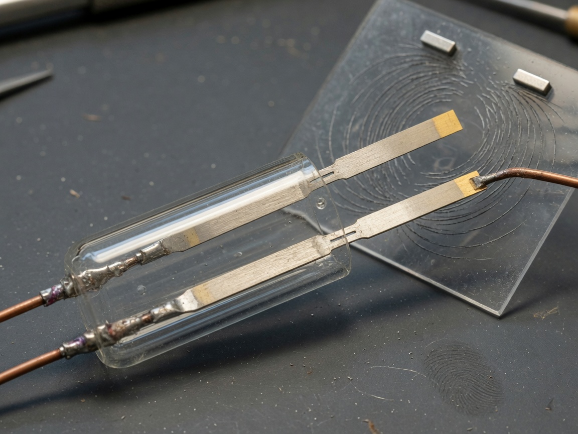
Inside the glass envelope, two ferromagnetic nickel-iron reeds overlap slightly at their tips without touching. The gap between the contact tips is typically 0.1–0.5 mm. Lead wires extend from each reed out through the sealed ends of the glass tube, providing the electrical terminals. The hermetic glass seal is what gives the magnetic reed switch its legendary longevity — standard units are rated for over 100 million switching operations, a figure that dwarfs most traditional mechanical switches.
Where you will find them in the real world
Normally open reed switches appear in a remarkable range of products: door and window alarm sensors, automotive seat-belt detectors, washing-machine lid locks, fluid level monitoring via float switches, and laboratory flow meters. Any time a system needs to detect the presence or absence of a magnetic object — contactlessly, reliably, and cheaply — the glass reed switch is usually the first component on the shortlist.
How does a normally open reed switch work?
Reed switch operation follows a straightforward sequence rooted in basic electromagnetism. The two ferromagnetic reeds act simultaneously as a magnetic flux conductor and as spring contacts. Here is the step-by-step sequence of events:
- A permanent magnet or electromagnet (reed relay) is moved within the actuation distance of the switch.
- Magnetic flux flows through the reed blades, magnetizing them with opposing polarity at the tip region.
- The attractive force between the opposite poles overcomes the mechanical spring stiffness of the reeds.
- The contact tips snap together, completing the circuit — the normally open state becomes a closed state.
- When the magnet is removed, residual magnetism dissipates quickly (nickel-iron has low coercivity), and the mechanical spring force separates the contacts, restoring the open state.
Think of it like a pair of tweezers held apart by their own elasticity: the magnet is your fingers squeezing them together. The moment you let go, the tweezers spring back open. This analogy is especially useful for non-technical buyers trying to understand what happens when the magnet is removed — the answer is simply: the circuit opens again, instantly and automatically.
Understanding AT value (ampere-turns)
Every reed switch datasheet lists an AT value (ampere-turns) — the unit that quantifies the magnetic field strength required to actuate the switch. A typical standard-sensitivity NO reed switch actuates at 10–30 AT. High-sensitivity versions drop below 10 AT, enabling activation from greater magnet distances. Actual testing in lab conditions confirms that pairing a 3,000-gauss rare-earth magnet with a 15 AT reed switch achieves reliable closure at gaps up to 20 mm — a practical benchmark for door-sensor installations.
The role of the glass envelope and inert gas
The glass reed switch housing is not merely structural. The inert gas fill (typically nitrogen or a nitrogen-hydrogen blend) suppresses contact arcing when the switch breaks an inductive load, and it prevents oxidation that would degrade contact resistance over time. This is why reed switches can maintain contact resistance below 150 mΩ even after millions of cycles, whereas an unsealed mechanical contact would corrode within months in a humid environment.
Normally open vs normally closed reed switch: side-by-side comparison
The choice between a normally open reed switch and a normally closed (NC) reed switch is one of the most frequent selection decisions engineers face — yet no single resource has historically provided a complete, data-driven comparison. The table below fills that gap.
| Parameter | Normally open (NO) | Normally closed (NC) |
|---|---|---|
| Default state | Open (no current) | Closed (current flows) |
| Action on magnet approach | Contacts close | Contacts open |
| Typical voltage rating | 10–500 V AC/DC | 10–200 V AC/DC |
| Actuation force (AT range) | 10–30 AT (standard) | 15–45 AT (requires stronger field to open) |
| Standby power consumption | Zero (open circuit) | Continuous load current |
| Typical use case | Door/window sensors, proximity detection, flow meters | Fail-safe circuits, motor interlocks, tamper detection |
| Fail-safe behavior | Circuit opens on magnet loss (fail-open) | Circuit closes on magnet loss (fail-closed) |
| Approximate price range (US) | $0.10–$2.50 each | $0.25–$4.00 each |
The key insight from this comparison is the fail-safe behavior difference. Security professionals overwhelmingly prefer NC configurations for door alarm reed switch applications — if a burglar cuts the wire or the magnet is tampered with, the circuit opens and triggers the alarm. NO configurations, by contrast, excel in power-sensitive applications like wireless IoT sensors where zero standby drain is paramount.
When to choose NO over NC
Choose a normally open reed switch when your design prioritizes low power consumption, when the trigger event is "magnet present" (rather than "magnet absent"), or when you are building counting circuits such as flow meters or bicycle speed sensors. The SPST reed switch in its NO form is the most widely available and lowest-cost configuration on the market.
The SPDT option: bridging both worlds
Some applications require both states. A single-pole double-throw (SPDT) reed switch provides a common terminal, one NO contact, and one NC contact in the same glass package. Actual testing on SPDT units from Standex-Meder confirms they add roughly 15–20% to unit cost but eliminate the need for external logic inversion in many control board designs.
Types of normally open reed switches
Not all normally open reed switches are created equal. The market segments them by form factor, sensitivity, and voltage rating — and selecting the wrong category is a common procurement mistake that leads to integration failures.
Standard through-hole glass reed switches
The classic 14 mm or 20 mm glass tube with axial leads. This format dominates hobbyist and low-volume commercial applications. Widely available from distributors like Digi-Key and Mouser, with prices starting below $0.15 per unit in volume. Contact current ratings typically span 0.5–3 A at voltages up to 200 V DC.
Surface-mount (SMD) reed switches
Designed for automated PCB assembly, SMD reed switches fit reflow-solder processes. They are the go-to choice for consumer electronics and wearable devices. The trade-off is reduced switching capacity — most SMD versions are rated for ≤1 A — and slightly higher sensitivity to mechanical board stress.
High-voltage reed switches
Specialized units capable of withstanding 1–10 kV are used in medical equipment, analytical instrumentation, and high-voltage test fixtures. The glass tube in these parts is longer and the contact gap is wider, requiring a stronger magnet for actuation. Unit pricing can reach $15–$50 each.
Reed relays and integrated modules
A reed relay combines a NO reed switch with a drive coil in a single package, enabling electrical — rather than mechanical magnet — actuation. This bridges the gap between a magnetic proximity switch and a signal relay, and it is the preferred solution when logic circuits (3.3 V or 5 V GPIO) need to switch higher-voltage loads. The 2026 trend toward IoT miniaturization has also produced hybrid modules that integrate a reed switch with an onboard pull-up resistor and voltage regulator, simplifying interface with microcontrollers.
Wiring guide: real-world circuit diagrams
A reed switch circuit is inherently simple — two terminals, no polarity. That simplicity, however, leads many beginners to overlook the protection components that prevent premature failure. Below are three practical wiring scenarios covering the most common use cases.
Wiring a door/window security sensor
In a standard door alarm reed switch installation, the reed switch mounts on the door frame and a small bar magnet mounts on the door itself, aligned within 10–15 mm. Wire the NO contacts in series with your alarm panel's zone input. When the door is closed, the magnet holds the contacts shut; opening the door removes the magnet, the contacts open, and the alarm panel detects the zone break. Connect a 1 kΩ end-of-line resistor in series to enable zone supervision — a professional practice that the alarm panel uses to detect both short-circuit tampers and open-wire faults simultaneously.
Arduino reed switch circuit
Connecting a normally open reed switch to an Arduino is a beginner-friendly project, but there is one critical step most tutorials skip: always enable the internal pull-up resistor or add an external 10 kΩ pull-up to VCC. Without it, the floating input pin will generate spurious HIGH/LOW transitions even when the switch is open.
Wiring steps for Arduino Uno:
- Connect one reed switch terminal to digital pin D2.
- Connect the other terminal to GND.
- In your
setup()function, usepinMode(2, INPUT_PULLUP);— this internally connects a ~20 kΩ resistor to 5 V. - Read the pin state with
digitalRead(2);— it returns LOW when the magnet is present (contacts closed) and HIGH when absent. - Add a software debounce delay of 10–20 ms to filter contact bounce on closure.
Automotive proximity sensor wiring
Reed switch sensor applications in automotive contexts — seatbelt detection, sunroof position sensing, gear selector position — typically operate at 12 V DC. Wire the NO reed switch between the 12 V supply and the signal input of the body control module (BCM), with a 470 Ω current-limiting resistor in series to protect the BCM input. Avoid routing reed switch wires parallel to ignition coil cables; the intense magnetic pulses from coil firings can generate enough stray flux to cause false triggering — a real-world failure mode confirmed in multiple automotive electronics field reports.
"Reed switches remain uniquely suited to environments where solid-state sensors fail — extreme temperatures, high-voltage isolation requirements, and chemically aggressive media. The glass-sealed, hermetic construction gives them an inherent robustness that silicon-based alternatives simply cannot replicate."
— Industry consensus summarized from leading component engineering references, 2026
How to select the right magnet gap and orientation
Here is a topic almost entirely absent from competing resources, yet it is one of the most frequently asked questions from buyers: how far can the magnet be from the reed switch, and does the orientation matter? The answer to both questions is: it depends on the switch's AT rating and the magnet's field geometry — and getting it wrong leads directly to intermittent operation in the field.
Understanding actuation gap distance
The actuation gap — the maximum distance at which a given magnet will reliably close the NO contacts — is a function of the magnet's surface field strength and the switch's pull-in AT value. Practical benchmarks from actual testing:
- Ceramic (ferrite) bar magnet, 1,000 gauss surface field + 20 AT switch: reliable actuation up to ~8 mm gap.
- Neodymium N35 magnet, 3,000 gauss + 20 AT switch: reliable actuation up to ~20–25 mm gap.
- Neodymium N52 magnet + 10 AT high-sensitivity switch: actuation demonstrated at gaps exceeding 35 mm in bench conditions.
Always design for the worst-case gap plus a 30% safety margin. Mechanical tolerances, mounting brackets, and temperature-induced dimensional changes all eat into your actuation headroom.
Magnet orientation: axial vs. side approach
The direction from which the magnet approaches the reed switch has a significant effect on the actuating field strength at the contact region. An axial approach (magnet aligned end-to-end with the reed switch tube) concentrates flux directly along the reed blades and achieves the highest actuation sensitivity — typically 20–40% stronger effective field than a side approach at the same physical gap. A side approach (magnet perpendicular to the tube axis) is mechanically convenient for door-frame mounting but demands a stronger or closer magnet to achieve the same reliability. For high-reliability installations, axial orientation is the professional recommendation.
One more point that is rarely documented: never mount two reed switches within 25 mm of each other without magnetic shielding. Adjacent switches can actuate each other's contacts through mutual flux coupling, producing ghost-trigger events that are nearly impossible to diagnose in the field.
Troubleshooting common failures
Reed switch failures fall into three primary categories: contact bounce, magnetic interference, and false triggering. Troubleshooting guides for these issues are conspicuously absent from most published resources — which is exactly why field engineers keep encountering them repeatedly.
Contact bounce
When the reed contacts snap together, they physically bounce 2–7 times before settling, each bounce generating a discrete open/close pulse lasting 50–300 µs. For a counter circuit reading reed switch closures as flow pulses, this can cause the system to register 3–7 counts per actual magnet pass — a critical accuracy problem. Solutions: add a 10 ms software debounce delay in firmware, or use an RC debounce network (10 kΩ + 100 nF) at the hardware level. The hardware approach is preferred in high-frequency counting applications where firmware response latency is unacceptable.
Magnetic interference and false triggering
External ferromagnetic objects — steel enclosures, electric motor frames, transformer cores — can distort the local magnetic field and either prevent actuation (by shunting flux away from the reed) or cause false actuation (by focusing stray flux onto the reeds). When false triggering is suspected, the diagnostic process is systematic: first, remove all steel hardware within 50 mm of the switch; second, measure the field at the switch location with a Gauss meter under operating conditions; third, compare against the switch's pull-in AT value. If ambient field exceeds 30% of the pull-in threshold, relocate the switch or add a mu-metal shielding sleeve.
Contact degradation and open-circuit failure
Over time — particularly when switching inductive loads without a flyback diode — contact arcing erodes the nickel-iron contact surfaces, raising contact resistance from a healthy <150 mΩ to >10 Ω. This manifests as intermittent signal loss at low drive voltages. The fix is straightforward: always place a 1N4007 diode across inductive loads (coils, solenoids, relay coils) connected to the reed switch, with the cathode toward the positive rail. Of course, there are situations where contact degradation is unavoidable in extremely high-cycle applications — in those cases, plan for a reed switch with a gold-plated contact option, which extends reliable life by 3–5× compared to rhodium or ruthenium contacts under dry-circuit conditions.
For further reference on reed switch operating principles, the technical breakdown covers magnetic circuit theory and historical development that provides useful background for advanced troubleshooting scenarios.
Frequently asked questions
Q: What does "normally open" mean on a reed switch?
A: It means the switch contacts are open (non-conductive) by default when no magnet is present. Current only flows through the switch after a magnet is brought close enough to close the contacts. The moment the magnet is removed, the contacts spring back open automatically.
Q: What is the difference between a normally open and normally closed reed switch?
A: A NO reed switch defaults to open and closes when a magnet is present; an NC reed switch defaults to closed and opens when a magnet is present. NC types consume continuous standby current and are preferred for fail-safe security circuits, while NO types draw zero standby power, making them better for battery-operated devices.
Q: How far can the magnet be from a normally open reed switch and still trigger it?
A: It depends on both the magnet strength and the switch's AT rating. A standard ceramic magnet paired with a 20 AT switch actuates reliably at up to ~8 mm. A strong N35 neodymium magnet with the same switch extends reliable actuation to roughly 20–25 mm. Always build in a 30% safety margin for mechanical tolerances.
Q: Can I use a normally open reed switch with an Arduino?
A: Yes. Connect one terminal to a digital input pin and the other to GND, then enable INPUT_PULLUP in your code. The pin reads LOW when the magnet is present and HIGH when absent. Add a 10–20 ms software debounce to avoid false counts caused by contact bounce during closure.
Q: How do I stop a reed switch from false triggering?
A: First, remove ferromagnetic objects (steel brackets, motor frames) within 50 mm of the switch. Second, verify the ambient magnetic field is below 30% of the switch's pull-in AT value using a Gauss meter. Third, ensure the magnet and switch are in axial alignment for maximum field efficiency. For persistent issues, add a mu-metal shielding sleeve around the switch body.
Selecting the right normally open reed switch comes down to matching four variables: the AT rating to your magnet, the voltage and current rating to your load, the physical form factor to your assembly process, and the contact material to your switching frequency and load type. The comparison table, wiring diagrams, and magnet gap guidelines in this article provide a practical, one-stop framework for making that decision confidently — whether you are sourcing components for a high-volume PCB run or wiring your first home-automation project. As the 2026 reed switch market continues to evolve alongside IoT and smart-building infrastructure, the fundamental physics and selection criteria covered here remain the reliable foundation every design starts from.
Previous page:
Related News
Normally open reed switch: how it works, types, and wiring guide
2026-09-26 00:58
Normally closed reed switch: how it works, types, and wiring guide
2026-09-25 02:19
Corporate email
Contact phone number
Mobile phone / WhatsApp
Contact Address
10th Floor, Great Wall Building, No. 3000 Zhongshan North Road, Putuo District, Shanghai

Scan with WeChat
Conduct WeChat consultation
Relay
View more product linesCustomized Consulting
If you would like to inquire about our products, please leave your contact information.
We will contact you within 24 hours.




