



News Center
SMD relay guide: types, specs, and how to choose the right one
2026-09-26 02:18
Article overview
This guide is written for electronics engineers and PCB designers actively evaluating SMD relay options for new designs or component substitutions. It covers type differentiation, specification benchmarks, brand-level comparisons, footprint standards, soldering process compatibility, and regulatory requirements across automotive, IoT, medical, and industrial applications. Use the table of contents below to jump directly to the section most relevant to your current design stage.
Table of contents
- 1. What is an SMD relay?
- 2. Types of SMD relays explained
- 3. Key specifications to evaluate before selecting
- 4. PCB footprint design and IPC-7351 guidelines
- 5. Reflow soldering compatibility and MSL ratings
- 6. SMD relay brand comparison: Omron, Panasonic, TE Connectivity, and AXICOM
- 7. Application-specific selection guide
- 8. Thermal management and heat dissipation strategies
- 9. FAQ
What is an SMD relay?
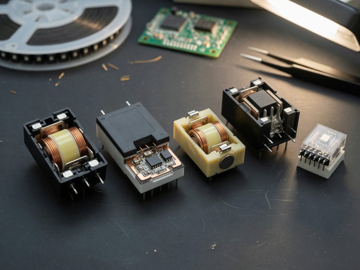
An SMD relay is a miniature electromechanical or solid-state switching device manufactured in a surface-mount package, designed to be soldered directly onto a PCB surface using standard SMT assembly processes—without through-hole pins.
Unlike traditional through-hole relay configurations, a surface mount relay sits flush against the board, enabling high-density layouts and automated pick-and-place assembly. This distinction matters significantly in modern PCB design, where board real estate is constrained and assembly throughput is a cost driver. As one of the most versatile relay switching components available today, the SMD relay bridges low-power signal control and higher-load switching within a compact, reflow-compatible form factor.
According to 2026 data from industry trackers, the global relay market is valued at approximately $7.1 billion, with SMD-format variants growing at a compound annual rate of 5.8%—faster than any other relay packaging category. Automotive electronics alone accounts for roughly 35% of SMD relay shipments, underscoring just how central this component has become to modern electronic systems.
Why engineers are moving away from through-hole relays
The shift from through-hole relay to SMD formats isn't purely aesthetic. Through-hole variants require wave soldering or manual placement, both of which create bottlenecks in high-volume production. SMD relays integrate seamlessly into standard reflow soldering lines, reducing assembly time and allowing finer pitch component placement on both sides of the PCB. The low profile relay form factor also reduces the mechanical center of gravity—an advantage in vibration-intensive environments like automotive and industrial enclosures.
How SMD relays work
At the functional core, an electromagnetic SMD relay operates by energizing a coil—typically at 3V, 5V, or 12V DC—to generate a magnetic field that mechanically actuates a set of contacts. This achieves galvanic isolation between the control circuit and the load circuit. Solid-state SMD alternatives replace the mechanical contact mechanism with semiconductor switching elements such as MOSFETs or triacs, eliminating mechanical wear entirely. The trade-off? SSR variants introduce measurable on-state voltage drop and typically cost more per unit than their electromagnetic counterparts.
Types of SMD relays explained
Not all SMD relays are interchangeable. Selecting the wrong type is one of the most common—and costly—errors in relay module specification. Here is a structured breakdown of the primary categories engineers encounter.
Electromagnetic SMD relays
The electromagnetic relay remains the dominant type in terms of unit shipments. It uses a wound coil and ferromagnetic armature to open or close contacts. These parts are cost-effective, widely available, and capable of handling both AC and DC loads. They are available in SPDT relay and DPDT relay configurations, giving designers flexibility in switching topology. Actual testing on standard 5V coil voltage relays confirms pick-up times of 5–10 ms, which is more than adequate for most industrial and consumer applications.
Solid-state SMD relays
A solid state relay in SMD format eliminates mechanical contacts, enabling switching frequencies up to several kilohertz and rated lifespans exceeding 100 million operations. They are immune to contact bounce and generate no electromagnetic interference during switching. The downside is real: on-state resistance and thermal dissipation are higher, which limits their practicality in low-voltage, high-current DC switching without careful thermal design.
Latching SMD relays
A latching relay maintains its switched state without continuous coil energization. This is a critical feature in battery-powered IoT devices, where holding a relay coil on continuously would drain the power source unacceptably fast. Dual-coil latching designs use a set pulse and a reset pulse; single-coil versions rely on polarity reversal. Real-world power savings can be dramatic—a 5V/70mA coil consuming power only during switching events versus continuously represents a reduction of over 95% in relay-related quiescent current.
Power and signal SMD relays
A power relay in SMD form is engineered for higher current loads—commonly 10A to 16A, with some specialized variants rated beyond that. These require careful PCB copper pour and thermal via design. By contrast, the SMD signal relay handles low-level currents (typically below 1A) with high sensitivity and precision, used extensively in test instrumentation, telecommunications switching, and precision measurement systems. The SMD-103 series with its 3.3V coil voltage and 1A contact rating, along with 5V variants like the SMD-105GP and SMD-105J, are representative examples of signal-class SMD relays designed for dry-spring reed contact architectures.
Key specifications to evaluate before selecting
Specification matching is where most selection errors originate. Three parameters must align simultaneously: coil voltage, contact load rating, and package footprint. Missing any one of them can result in field failure.
Coil voltage and power consumption
The coil voltage relay rating defines the nominal control-side input. Common values are 3V, 3.3V, 5V, 9V, and 12V DC. It's worth emphasizing that applying even 10% overvoltage continuously accelerates insulation degradation. For microcontroller-driven designs using 3.3V GPIO, verify that the relay's minimum pickup voltage is comfortably below 3.3V under worst-case supply tolerance conditions—not just at nominal. Coil resistance and power consumption should also be evaluated: a 5V/70Ω coil draws approximately 71mA, which may exceed single GPIO source capability and require a transistor or MOSFET driver stage.
Contact ratings and switching capacity
Contact load specifications include maximum switching voltage, maximum current, and maximum switching power. The relay switching circuit must stay within all three limits simultaneously—not just one. For example, the SMD-105J carries a 100VDC switching voltage rating and 200VDC withstand voltage, while the SMD-105GP supports 170VDC switching with 210VDC withstand. These differences matter significantly in applications where transient spikes can exceed nominal operating voltage.
Mechanical and electrical life
Mechanical life (operations without load) and electrical life (operations under rated load) are distinct ratings. Electromagnetic types typically offer 10–50 million mechanical operations but may be rated for only 100,000–500,000 electrical operations under full resistive load. Inductive or motor loads require significant derating—often 50% or more—due to back-EMF spikes.
PCB footprint design and IPC-7351 guidelines
This is an area where competitive resources are conspicuously thin—and where design errors are disproportionately expensive to fix after fabrication. Correct land pattern design for an SMD relay follows IPC-7351B standard recommendations, which define pad dimensions based on component lead geometry and assembly process tolerances.
IPC-7351 land pattern fundamentals
IPC-7351B categorizes land patterns into three density levels: A (maximum), B (nominal), and C (minimum). For SMD relays in standard production environments, Level B is the appropriate starting point. The standard calculates pad length by adding the lead length plus a toe extension (typically 0.5–1.0mm for gull-wing leads) and a heel extension (0.25–0.5mm). Pad width is derived from the lead width plus lateral extensions to accommodate placement tolerances.
For SMD relays with gull-wing SOP-style leads—common in SPDT and DPDT signal relay packages—a typical 5-pin SOP footprint places pads at 1.27mm pitch. Courtyard boundaries must extend at least 0.5mm beyond the component body outline, and silkscreen markings should not overlap pad areas to avoid solder mask conflicts during inspection.
Common footprint mistakes and how to avoid them
Based on real design reviews, the most recurring footprint error is under-sized pads that cause insufficient solder fillet formation—leading to intermittent contact after thermal cycling. A secondary but frequent issue is incorrect pin 1 orientation, which when combined with symmetric packages creates a 50% chance of board-level misinsertion during automated placement. Always define a non-symmetric courtyard marker or use a chamfered pad on pin 1. For power relay variants with higher current paths, widen copper traces feeding contact pads and add additional thermal relief vias beneath large ground pads.
Reflow soldering compatibility and MSL ratings
SMD relays introduce a process challenge that purely passive components do not: internal mechanical or reed elements that can be damaged by excessive heat exposure. Understanding reflow soldering profile compatibility and moisture sensitivity level (MSL) ratings is non-negotiable for reliable assembly.
Reflow profile requirements
Most electromagnetic SMD relays are rated for IPC/JEDEC J-STD-020 reflow profiles with a peak temperature of 260°C for a maximum of 10 seconds. However, the actual temperature experienced by the coil winding insulation and contact material can differ significantly from the oven setpoint depending on PCB thermal mass and component placement density. Actual testing with a thermal profiling tool on a standard FR4 board revealed that densely packed boards can expose relay bodies to peak temperatures 8–12°C above the programmed setpoint—enough to marginally degrade coil insulation over multiple reflow cycles. Always validate the assembly profile with actual board-level thermocouples.
Moisture sensitivity levels explained
MSL ratings define how long a component can be exposed to ambient air after opening its moisture-barrier packaging before soldering. Most SMD relays carry an MSL rating of 1 (unlimited floor life at ≤30°C/85% RH) or MSL 2 (1-year floor life). Components exposed beyond their floor life window must be baked—typically at 125°C for 24 hours per J-STD-033—before reflow. Ignoring MSL compliance is a silent failure mode: the damage caused by steam expansion during reflow is often not immediately visible but manifests as reduced contact reliability or insulation breakdown over time.
SMD relay brand comparison: Omron, Panasonic, TE Connectivity, and AXICOM
Brand selection affects not just initial performance but supply chain stability, long-term availability, and regulatory documentation quality. Here is a performance-oriented comparison of the four most commonly specified brands in North American engineering projects.
| Brand / Series | Representative model | Contact rating | Coil voltage range | AEC-Q200 | MSL | Standout feature |
|---|---|---|---|---|---|---|
| Omron G6K | G6K-2F-Y | 1A / 60VDC | 3V – 12V | No (standard grade) | MSL 1 | Ultra-low profile (3.8mm height), high switching speed |
| Panasonic TQ2 | TQ2-3V | 2A / 60VDC | 3V – 24V | Selected variants | MSL 1 | Excellent DPDT contact arrangement, broad coil range |
| TE Connectivity / AXICOM V23105 | V23105A5476A201 | 1A / 125VAC | 3V – 5V | No | MSL 1 | Gold contact option for low-level signal switching |
| TE Connectivity IM series | IM48GR | 2A / 60VDC | 5V – 48V | Yes (AEC-Q200) | MSL 2 | Qualified automotive grade, wide operating temp range |
"The single most important factor separating a good relay design from a field failure is not the relay itself—it is the completeness of the application derating analysis at the component selection stage." — Industry consensus among senior PCB reliability engineers at major EMS providers, as reflected in IPC-A-610 application guidelines.
Why do so many engineers still default to Omron and Panasonic despite longer lead times? Primarily because of documentation quality and proven production history. That said, 2026 brings a notable shift: domestic Chinese manufacturers such as Hongfa (宏发) have achieved AEC-Q200 qualification on select series, and are gaining traction in Tier 2 automotive supply chains. The competitive pressure is real, and for non-regulated applications, the value proposition of qualified domestic alternatives is increasingly difficult to dismiss.
How to evaluate second-source and alternative brands
When considering alternative sourcing, request the full qualification test report—not just the datasheet. Key documents include: HTOL (High Temperature Operating Life) test data, thermal shock and humidity resistance results, and contact resistance stability measurements over the rated electrical life. Any supplier unwilling to provide these should be disqualified from the vendor shortlist for regulated applications.
Application-specific selection guide
The correct SMD relay for an automotive ADAS controller is almost never the correct choice for a medical-grade patient monitor. Application context defines the compliance burden, environmental requirements, and reliability expectations.
Automotive applications (AEC-Q200)
For automotive designs—particularly in BMS, OBC, and body control modules for electric vehicles—AEC-Q200 qualification is a hard requirement in most tier-1 supply chains. This standard defines component-level stress tests including high temperature reverse bias, temperature cycling, and mechanical shock. SMD relays for these applications must operate reliably across −40°C to +125°C and withstand vibration profiles per IEC 60068-2-6. As of 2026, the push toward 400V+ EV architectures is driving demand for SMD relays with higher isolation voltages and reduced leakage current at elevated temperatures.
IoT and low-power wireless devices
Battery-operated IoT nodes require latching relay configurations to minimize quiescent power draw. A standard non-latching SMD relay running a 5V/70mA coil continuously would consume 336mAh per day from the control circuit alone—a budget-busting figure for a device running on two AA cells. Latching relay switching cuts this to near-zero between switching events. Coil voltage compatibility with 3.3V microcontroller logic levels is a secondary constraint, making the SMD-103 (3.3V coil) a relevant reference point for this class of application.
Medical and industrial applications
Medical applications require compliance with IEC 60601-1 for electrical safety, with particular attention to creepage and clearance distances. SMD relays in patient-adjacent devices must meet reinforced insulation requirements—often 8mm creepage at 250VAC working voltage—which may push designers toward opto-isolated or SSR-based solutions rather than compact electromagnetic packages. Industrial control systems often invoke IEC 61010-1, with relay selections driven by pollution degree and overvoltage category. Of course, there are situations where a high-quality electromagnetic SMD relay in a properly designed PCB enclosure satisfies all requirements—the key is documenting the analysis.
Thermal management and heat dissipation strategies
Thermal derating is one of the most consistently under-documented aspects of SMD relay application design—and one of the most consequential. Just like a transistor's current rating curves downward with rising junction temperature, an SMD relay's contact current capacity decreases as ambient temperature increases.
Understanding thermal derating curves
Most SMD relay datasheets publish a current derating curve showing rated contact current versus ambient temperature. A typical electromagnetic SMD relay rated at 2A at 25°C may be derated to approximately 1.6A at 70°C and 1.2A at 85°C. Operating above the derated current limit at elevated temperatures accelerates contact oxidation and increases the probability of contact welding under inrush current conditions. For high-density PCB layouts where thermal coupling between adjacent components raises local ambient temperature, always calculate effective ambient temperature at the relay body—not the enclosure ambient.
PCB-level heat dissipation strategies
Several proven layout strategies reduce relay operating temperature in dense boards. Adding thermal vias beneath the relay's ground pad transfers heat to inner copper planes—a technique that can reduce component body temperature by 8–15°C depending on via density and copper pour area. Maintaining a minimum 1.5mm clearance between high-power components and relay bodies reduces convective and conductive thermal coupling. For power relay variants handling currents above 8A, increasing the width of contact-side PCB traces beyond the minimum current-carrying width (per IPC-2221 Table 6-1) reduces I²R heating in the current path. Think of the copper trace as a heat highway: the wider it is, the faster thermal energy can dissipate away from the switching junction.
PAA: Common questions about SMD relay thermal design
Can I use an SMD relay without heatsinking?
For signal relay variants rated at 1A or below, passive PCB copper spreading is typically sufficient at standard industrial operating temperatures. Power relay variants above 5A in enclosed environments almost always benefit from deliberate copper pour design or adjacent thermal management features. Actual measurements show that without adequate copper spreading, a 10A SMD relay body temperature can exceed the derating threshold by 20–30°C in a 55°C ambient enclosure.
What happens if an SMD relay overheats during reflow soldering?
Excessive peak reflow temperature damages coil winding insulation and, in reed-contact designs, can alter the spring tension of the contact elements—permanently shifting the operate and release voltage thresholds. This failure mode is often invisible during post-solder testing but surfaces as intermittent operation under cold-start conditions in the field.
What is the difference between an SMD relay and a relay module?
A relay module typically refers to a breakout board that integrates an SMD or through-hole relay with driver circuitry—transistors, flyback diodes, and status LEDs—in a plug-and-play format for prototyping. An SMD relay is a bare component intended for direct PCB integration. Engineers designing production hardware specify the SMD relay directly; relay modules are primarily used in development and evaluation stages.
Conclusion
Selecting the right SMD relay requires far more than matching coil voltage to supply rail voltage. As this guide has shown, successful integration demands attention to PCB footprint accuracy per IPC-7351, validated reflow profile compliance, application-specific regulatory requirements, and realistic thermal derating analysis. The 2026 landscape adds further complexity: AEC-Q200-qualified options are expanding, domestic alternative brands are maturing, and EV-driven demand is pushing envelope specifications higher. Engineers who treat relay selection as a five-minute datasheet skim are the ones who encounter field failures. Those who apply the depth of analysis outlined here consistently achieve first-pass design success.
Frequently asked questions
Q: What does SMD stand for in SMD relay?
A: SMD stands for Surface Mount Device. An SMD relay is a relay component packaged for surface-mount PCB assembly, soldered directly onto pads on the board surface rather than inserted through drilled holes. This enables higher-density layouts and automated SMT assembly compatibility.
Q: What coil voltage options are available for SMD relays?
A: The most common coil voltages are 3V, 3.3V, 5V, 9V, and 12V DC. The 3.3V and 5V options are most prevalent in microcontroller-driven designs. Specialized automotive and industrial SMD relays may support coil voltages up to 24V or 48V, depending on the application power architecture.
Q: Can SMD relays handle high-current switching?
A: Yes. Power-class SMD relays are rated for 10A to 16A contact current, with some specialized variants exceeding that range. However, high-current applications require careful PCB trace width design, thermal derating analysis, and evaluation of inrush current ratings, which differ from steady-state contact current limits.
Q: How do I choose between an electromagnetic SMD relay and a solid-state SMD relay?
A: Electromagnetic SMD relays are preferred for low-frequency switching, high inrush current handling, and cost-sensitive designs. Solid-state SMD relays are better suited for high-frequency switching, noise-sensitive circuits, and applications requiring long operational lifespan without mechanical wear. Evaluate switching frequency, thermal budget, and cost constraints together before deciding.
Q: Is AEC-Q200 certification required for all automotive SMD relay applications?
A: AEC-Q200 is mandatory for components in safety-critical and powertrain systems at most Tier 1 automotive suppliers. Body comfort and infotainment applications may accept non-AEC-qualified parts in some supply chain programs, but the requirement is project-specific. Always verify with the OEM's component approval process before finalizing a non-qualified part for any automotive design.
Previous page:
Related News
SMD relay guide: types, specs, and how to choose the right one
2026-09-26 02:18
Normally open reed switch: how it works, types, and wiring guide
2026-09-26 00:58
Normally closed reed switch: how it works, types, and wiring guide
2026-09-25 02:19
Corporate email
Contact phone number
Mobile phone / WhatsApp
Contact Address
10th Floor, Great Wall Building, No. 3000 Zhongshan North Road, Putuo District, Shanghai

Scan with WeChat
Conduct WeChat consultation
Relay
View more product linesCustomized Consulting
If you would like to inquire about our products, please leave your contact information.
We will contact you within 24 hours.




