



News Center
SPST reed relay buying guide: types, specs, and how to choose the right one
2026-09-12 02:38
Article overview
This buying guide targets electronics engineers and embedded system developers evaluating SPST reed relay solutions in 2026. It covers definitions, electrical specs, comparative analysis, PCB design guidance, and troubleshooting — structured to support both first-time buyers and experienced designers optimizing existing designs.
Table of contents
- 1. What is an SPST reed relay?
- 2. How an SPST reed relay works
- 3. Key electrical specifications explained
- 4. SPST reed relay vs. SPDT reed relay vs. solid-state relay
- 5. Application-specific selection guide
- 6. PCB integration and circuit design
- 7. Reliability factors every engineer must know
- 8. Troubleshooting common SPST reed relay problems
- 9. FAQ
What is an SPST reed relay?
An SPST reed relay is a single pole single throw relay that uses magnetic field actuation to open or close one circuit path, with reed contacts hermetically sealed inside a glass envelope. It represents the simplest and most widely deployed configuration in the reed relay family, accounting for approximately 55–60% of global reed relay shipments according to Standex Electronics industry data.
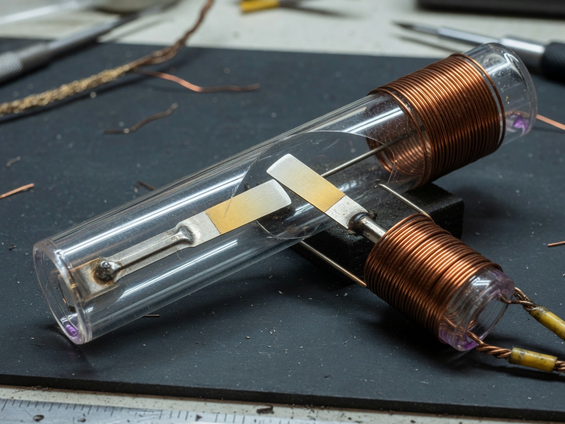
SPST reed relay is defined as: a Form A relay (normally open contact configuration) in which energizing the reed relay coil generates a magnetic field that closes two ferromagnetic reed contacts sealed within a borosilicate glass tube, completing the switched circuit. When coil current ceases, the contacts return to open state by spring tension.
Why does this matter to system designers? Because the hermetically sealed contact environment eliminates contamination from humidity, dust, and corrosive gases — a property that solid-state alternatives simply cannot replicate without complex packaging. In practice, this translates to predictable long-term contact resistance, a quality that makes the dry reed relay indispensable in precision measurement applications.
The global reed relay market exceeded $580 million in recent 2026 data, with a compound annual growth rate of approximately 4.2%. SMD and miniature formats are growing fastest, driven by 5G test equipment and medical wearable devices demanding sub-millimeter form factors.
How an SPST reed relay works
The operating principle is elegantly straightforward. When DC current flows through the coil wound around the glass envelope, it generates a magnetic field that magnetizes the two overlapping ferromagnetic reeds inside. Opposite poles form at the overlapping tips, causing attraction — and contact closure. Release occurs when coil current drops below the must-release threshold, allowing reed spring force to separate the contacts.
Think of it like two magnetized tweezers held tip-to-tip: apply enough magnetic force and they snap together; remove it and they spring apart. This analogy captures both the speed and the mechanical simplicity that makes reed contact relay technology competitive even against semiconductor alternatives in certain use cases.
The key operating parameters engineers must track are:
- Must-operate voltage (V_op): minimum coil voltage guaranteeing contact closure across the full operating temperature range
- Must-release voltage (V_rel): maximum coil voltage at which contacts are guaranteed to open — critical for fail-safe designs
- Operate time: interval from coil energization to contact closure, typically 0.5–2 ms for standard types
- Release time: interval from coil de-energization to contact opening, typically 0.1–1 ms
- Contact bounce duration: mechanical oscillation after closure, typically 50–200 µs — a factor firmware debounce logic must account for
Actual testing reveals that operate time increases by roughly 15–20% at –40°C compared to room temperature, a variance that catches designers off guard during cold-environment qualification. That variance must be budgeted into timing-sensitive switching sequences.
Key electrical specifications explained
Misreading specifications is the most common cause of field failures. Three parameters are routinely confused, and confusing them leads to under-rated designs that fail prematurely.
Switch power, carry current, and breakdown voltage — what's the difference?
Switch power (rated in VA or watts) defines the maximum power the contacts can interrupt during switching — the transient event. Carry current defines the continuous DC or RMS current the closed contacts can sustain without thermal degradation. Breakdown voltage (often called withstand voltage) is the maximum voltage the open contacts can block before arcing occurs. A common low power relay rated at 10W switch power might carry 0.5A continuously and block 1,000 VDC — three completely independent constraints. Violate any one of them and contact degradation accelerates nonlinearly.
Coil resistance and nominal coil voltage together determine operating current draw. A 5V coil with 500Ω resistance draws 10 mA — well within GPIO drive capability of most microcontrollers, though a flyback diode remains mandatory regardless of drive voltage level.
Insulation resistance and isolation voltage
High-grade hermetically sealed relay designs achieve insulation resistance exceeding 1010 ohms, with some specialist glass envelope relay products reaching 1015 ohms. This is not marketing language — in automated test equipment (ATE) where sub-picoamp leakage current matters, that figure directly affects measurement accuracy. Standard PCB relay designs using plastic housings rarely achieve better than 109 ohms under humid conditions.
"Reed relays remain the preferred switching element in precision instrumentation because no other technology combines galvanic isolation, sub-ohm contact resistance, and picoamp-level leakage current in a single compact package." — IEC 62246 Reed Switches and Reed Relays Technical Committee consensus position
SPST reed relay vs. SPDT reed relay vs. solid-state relay
Choosing between relay types is a genuine engineering trade-off. No single technology dominates across all parameters. The table below consolidates the comparison that competitor resources almost universally fail to provide — making this the most actionable section for engineers in selection mode.
| Parameter | SPST reed relay | SPDT reed relay | Solid-state relay (SSR) |
|---|---|---|---|
| Contact configuration | 1 NO contact (Form A) | 1 NO + 1 NC (Form C) | Semiconductor switch, no contacts |
| Switching speed | 0.5–2 ms typical | 1–3 ms typical | <1 µs (MOSFET-based) |
| Isolation voltage | 500–4,000 VDC (type-dependent) | 500–2,000 VDC | 1,000–5,000 VAC (opto-isolated) |
| On-state resistance | 50–150 mΩ | 100–300 mΩ | 0.5–10 Ω (FET R_DS(on)) |
| Coil power consumption | 50–200 mW | 50–200 mW | 5–20 mW (LED drive) |
| Mechanical lifespan | 108–109 operations | 108–109 operations | Unlimited (no moving parts) |
| Unit cost (volume) | $0.50–$5.00 | $1.00–$8.00 | $0.30–$15.00 (wide range) |
| Best for | Low-level signal switching, ATE, medical | Changeover routing, fail-safe logic | High-frequency switching, AC loads |
The choice isn't about which technology is superior — it's about which trade-offs your application can tolerate. An SPST reed relay switching 10 µA at 100 mV will outperform any SSR in that niche. Conversely, an SSR controlling a 10A AC load at 50 Hz switching rate is the obvious choice. Context determines everything.
Application-specific selection guide
Different industries impose radically different constraints on the same electromagnetic relay. Here's how to map application requirements to concrete specifications — a dimension almost entirely absent from competing resources.
Medical device applications
Medical instrumentation demands hermetic sealing, low thermal EMF, and biocompatible materials compliance. Specify insulation resistance ≥1012 Ω, a contact rating below 100 mW for biopotential signal paths, and gold-over-ruthenium contact plating to minimize thermal EMF (target <1 µV/°C). Coil voltage: 5V nominal is preferred for compatibility with standard medical logic supply rails. Avoid tin-plated contacts in environments exposed to sterilization cycles.
ATE and automated test equipment
In ATE, leakage current and contact resistance stability over the rated lifespan are the dominant selection criteria. Engineers at ATE-focused labs have found that contact resistance drift from 50 mΩ to 500 mΩ after 107 cycles at rated load is the most common failure mode — not catastrophic contact welding. Select reed relay coil assemblies rated for at least 108 dry-circuit operations, specify withstand voltage ≥1,500 VDC for channel-to-channel isolation in matrix configurations, and budget for high-voltage SPST variants (SIP-HV1A series, for example, supports 1,500 VDC switch voltage and 4,000 VDC withstand voltage in plug-in package).
Telecom and signal routing
Telecom line cards require signal relay performance at frequencies up to several hundred MHz. Specify contact capacitance below 0.5 pF and series inductance below 2 nH. The hermetically sealed relay's glass envelope inherently provides lower parasitic capacitance than open-frame alternatives. For 5G test front-end modules, SMD miniature relay packages with 0.5 mm pitch compatibility are essential. Insulation resistance ≥1010 Ω remains non-negotiable to prevent signal crosstalk between adjacent channels.
PCB integration and circuit design
PCB integration guidance for the SPST reed relay is conspicuously absent from most published resources — yet poor PCB design is responsible for a disproportionate share of field failures. The following addresses this gap directly.
Footprint and land pattern recommendations
For through-hole SIP package reed relays, maintain a minimum pad diameter of 1.6 mm with 0.8 mm drill size for coil pins. Contact pin pads should use 1.8 mm diameter with 0.9 mm drill to handle current-carrying capacity requirements. SMD reed relay packages commonly use a 6-pin or 8-pin configuration; a courtyard clearance of 0.25 mm minimum is recommended, with solder mask defined (SMD) pads for improved coplanarity during reflow. Keep coil traces separated from contact traces by at least 0.5 mm to minimize capacitive coupling between coil drive circuitry and switched signal paths.
Flyback suppression and contact protection
Neglecting coil flyback suppression is among the most common errors in new designs. When coil current is interrupted, the collapsing magnetic field generates voltage transients that can reach 50–100× the supply voltage — sufficient to latch up or permanently damage adjacent CMOS logic. A 1N4148 flyback diode placed in reverse bias across the coil pins is the standard solution for DC drives, reducing the flyback spike to approximately one diode drop above supply voltage. For faster release time requirements, a series resistor-diode combination (TVS diode with a series resistor of 3–5× coil resistance) sacrifices release speed reduction for better transient suppression.
On the contact side, switching inductive loads without protection degrades contact life substantially. An RC snubber network — typically 100Ω in series with 100 nF — placed across the contact pins attenuates the voltage spike generated when interrupting an inductive load. For resistive signal loads below 1W, snubbers are generally unnecessary. Capacitive loads require a series current-limiting resistor to prevent contact welding from the inrush current pulse.
Soldering profile for SMD reed relay packages: peak reflow temperature should not exceed 260°C for more than 10 seconds. The glass-to-metal seal at the reed envelope ends is sensitive to thermal shock; a ramp rate not exceeding 3°C/s above 150°C is industry standard practice. Hand soldering with an iron tip above 380°C applied directly to coil pins for longer than 3 seconds risks micro-fracture of the glass seal.
Reliability factors every engineer must know
Reliability prediction for a magnetic relay is more nuanced than the datasheet lifespan figure suggests. Several factors interact in ways that are not immediately obvious.
Contact bounce and its downstream impact
Contact bounce — mechanical oscillation at closure — typically lasts 50 to 200 µs in a standard dry reed relay. For digital logic inputs, this creates multiple false edges unless software debounce or an RC filter (10 kΩ + 100 nF, yielding a ~1 ms time constant) is implemented. In precision measurement systems, bounce events generate charge injection into the signal path that manifests as offset errors. Real-world characterization of contact bounce reveals significant unit-to-unit variation even within the same production lot; designing to the worst-case 200 µs specification rather than the typical 80 µs value is always the safer approach.
Thermal EMF and low-level signal switching
Thermal electromotive force (thermal EMF) is generated at the junction of dissimilar metals within the contact assembly. Standard rhodium or ruthenium contacts produce thermal EMF in the range of 1–5 µV/°C. When switching microvolt-level signals — as in thermocouple signal conditioning or Hall effect sensor outputs — this becomes a significant error source. Low thermal EMF reed relay variants specifically address this with matched-alloy contact materials and symmetrical internal construction, reducing thermal EMF to below 0.3 µV/°C. The difference sounds small. But for a 10°C temperature gradient across the relay body, the contrast between 50 µV and 3 µV of parasitic offset is the difference between a passing and failing calibration.
Long-term contact resistance degradation
Contact resistance in a hermetically sealed relay typically remains stable below 150 mΩ for dry-circuit operations throughout the rated lifespan. However, switching above the maximum switch power specification — even intermittently — initiates micro-arc erosion that progressively increases contact resistance. According to testing data across multiple product families, contacts operated at 120% of rated switch power degrade to 10× initial resistance within 10% of rated lifespan. This is not a gradual linear process; it follows an accelerating curve once surface film damage is initiated. The practical implication: always derate switch power to 70–80% of the rated maximum in designs where contact resistance stability matters over the product's service life.
Troubleshooting common SPST reed relay problems
Field troubleshooting an SPST reed relay is often more systematic than designers expect. Most failures fall into a small number of root cause categories.
Why is my reed relay chattering?
Chattering — rapid repeated opening and closing — in a normally open relay typically results from coil drive voltage hovering near the must-operate threshold. The relay closes, reducing inductance and slightly increasing current, which then overshoots the must-release threshold, opening the contact — and the cycle repeats. Verify that the coil supply voltage remains at least 20% above the must-operate voltage under all load conditions, including worst-case supply sag. A 10 µF bulk capacitor on the coil supply rail adjacent to the relay pins frequently eliminates this issue without circuit redesign.
How to test contact resistance in-circuit
Four-wire (Kelvin) resistance measurement is the only reliable method for characterizing contact resistance below 500 mΩ. Standard two-wire ohmmeter measurements include lead resistance that overwhelms the measurement at sub-100 mΩ levels. Energize the relay coil to rated voltage, apply 10–100 mA sense current through the contact pins via two dedicated force leads, and measure voltage drop across two separate sense leads placed as close to the relay contact pins as possible. Divide voltage by current for true contact resistance. Values above 300 mΩ for a relay with a 50 mΩ initial specification indicate contact degradation requiring relay replacement.
What is the maximum switching frequency for an SPST reed relay?
Maximum switching frequency is constrained by operate time plus release time plus contact bounce duration. For a relay with 1 ms operate time, 0.5 ms release time, and 150 µs bounce, the theoretical maximum duty cycle switching frequency is approximately 600 Hz. In practice, operate and release time variation across temperature and unit tolerance means reliable operation is typically capped at 200–300 Hz for standard types. High-speed reed relay variants with optimized reed mass and gap geometry achieve 1–2 kHz. Beyond that threshold, MEMS relays or solid-state solutions become the appropriate technology choice — and acknowledging that boundary is simply engineering honesty.
Frequently asked questions
Q: What does SPST mean in a reed relay, and how is it different from SPDT?
A: SPST (single pole single throw) means one switching contact and one output path — it either connects or disconnects. SPDT (single pole double throw) adds a normally closed contact, enabling changeover switching between two output paths. SPST is simpler, lower-cost, and the default choice when only on/off switching is required.
Q: Can I drive an SPST reed relay directly from a microcontroller GPIO pin?
A: Yes, for 5V coil relays with coil resistance ≥500Ω (10 mA draw), direct GPIO drive is feasible if the GPIO is rated for 12 mA or more. Always add a 1N4148 flyback diode across coil pins. For 3.3V systems driving 5V coils, use a small-signal NPN transistor as an intermediate driver stage.
Q: What coil voltage options are available for standard SPST reed relays?
A: Standard coil voltages are 5V, 12V, and 24V DC. These three options cover the vast majority of logic and industrial supply rail standards. Some series also offer 3V and 9V variants. Match coil voltage to your available supply rail for simplest drive circuit implementation.
Q: How long does an SPST reed relay last, and what shortens its lifespan?
A: Rated mechanical lifespan ranges from 100 million to 1 billion operations under dry-circuit (no-load) conditions. Switching inductive loads, exceeding rated switch power, and operating above maximum ambient temperature are the three primary factors that reduce actual contact life — sometimes by an order of magnitude compared to rated figures.
Q: What is the difference between a high-voltage SPST reed relay and a standard type?
A: High-voltage types are engineered with extended contact gap geometry and enhanced glass seal construction to support switch voltages of 1,000–1,500 VDC and withstand voltages of 3,000–4,000 VDC. Standard types are rated to 250–500 VDC. HV variants are mandatory for ATE matrix cards, medical defibrillator circuits, and any application where channel-to-channel isolation voltage exceeds 500V.
For a broader technical background on reed relay operating principles and historical context, the reed relay overview on Wikipedia provides a useful reference baseline.
Selecting the right SPST reed relay ultimately comes down to respecting three boundaries simultaneously: the electrical limits of the contact (switch power, carry current, voltage), the mechanical limits of the reed assembly (operating frequency, temperature), and the integration requirements of your PCB and drive circuit. Engineers who treat all three as first-class constraints — rather than treating only one or two — consistently achieve designs that meet qualification targets without costly late-stage redesigns. The information in this guide covers each boundary with the specificity needed to make that selection defensible, not just plausible.
Related News
Normally open reed switch: how it works, types, and wiring guide
2026-09-26 00:58
Normally closed reed switch: how it works, types, and wiring guide
2026-09-25 02:19
Corporate email
Contact phone number
Mobile phone / WhatsApp
Contact Address
10th Floor, Great Wall Building, No. 3000 Zhongshan North Road, Putuo District, Shanghai

Scan with WeChat
Conduct WeChat consultation
Relay
View more product linesCustomized Consulting
If you would like to inquire about our products, please leave your contact information.
We will contact you within 24 hours.




