



News Center
DPDT reed switch explained: types, wiring guide, and how to choose the right one
2026-09-10 09:31
Article overview
This guide provides a comprehensive technical and procurement reference for the DPDT reed switch in 2026. It covers product types, spec comparisons, magnetic actuation requirements, wiring configurations, failure-mode troubleshooting, and US distributor sourcing — written for electrical engineers and buyers at the supplier-evaluation stage.
Table of contents
- 1. What is a DPDT reed switch?
- 2. DPDT vs. SPDT vs. SPST: spec comparison
- 3. How DPDT reed switches work: magnetic actuation parameters
- 4. Wiring guide: common circuit configurations
- 5. Selecting the right DPDT reed switch for your application
- 6. Troubleshooting common failure modes
- 7. Sourcing and procurement guide for US buyers
- 8. FAQ
What is a DPDT reed switch?
A DPDT reed switch is a magnetically actuated, hermetically sealed switching component containing two independent sets of reed contacts, each capable of toggling between a normally open and normally closed position simultaneously. In plain terms: one magnet triggers two separate switching actions at the same time, which is precisely why this component is so useful in differential signal routing, motor direction control, and failsafe relay circuits.
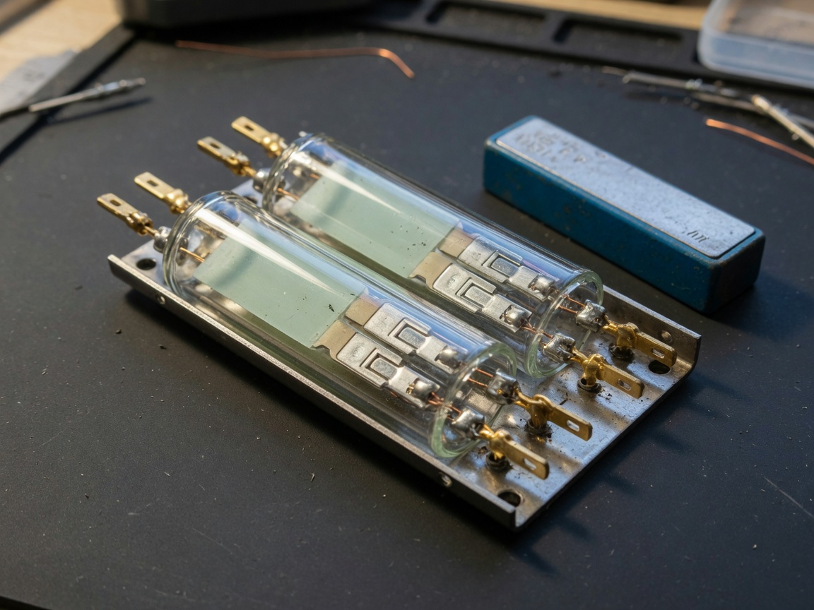
The glass envelope switch construction — a hallmark of all reed switch technology — encloses the ferromagnetic reed contacts inside an inert-gas-filled or vacuum-sealed borosilicate glass capsule. This sealed environment protects the contacts from oxidation, moisture, and contamination, delivering consistent performance across millions of switching cycles. According to reed switch operating principles, the basic mechanism dates back to Bell Labs in the 1940s, yet the underlying physics remain as relevant as ever.
Why does the DPDT configuration matter? Think of it like a railroad switch that controls two parallel tracks simultaneously — move the lever once, and both tracks reroute at the exact same instant. That synchronous dual-path switching is simply not achievable with two separate SPDT reed switches wired in tandem, because mechanical timing differences introduce millisecond-level skew that can corrupt sensitive signal chains.
The term double pole double throw switch describes the configuration precisely: "double pole" means two independent circuit poles (two input terminals), and "double throw" means each pole has two output positions. A DPDT relay or DPDT reed switch therefore has six terminals in total — two commons, two normally open contacts, and two normally closed contacts.
Key structural components
The glass envelope houses two reed blades made from a nickel-iron alloy. Each blade acts simultaneously as the spring mechanism, the magnetic armature, and one side of the electrical contact. When an external magnetic field reaches the actuation threshold, both blades flex inward, making or breaking contact. Remove the field, and the elastic memory of the metal returns the blades to their rest position. No coil, no solenoid, no mechanical pivot — just the inherent magnetic and elastic properties of the material itself.
Where it fits in the broader switching ecosystem
The DPDT reed switch belongs to the larger family of magnetically actuated switches, which includes SPDT reed switches, latching reed switches, and proximity switches. It sits above SPST and SPDT variants in complexity, and below full reed relays (which add a wound coil for remote electromagnetic actuation). Understanding this hierarchy matters when you are evaluating whether a DPDT reed switch is the correct signal switching component for your design — or whether a full reed relay with driver circuitry would be more appropriate.
2026 data from MarketsandMarkets estimates the global reed switch market will exceed $520 million, with DPDT configurations accounting for roughly 22% of industrial automation applications — a share that has grown steadily alongside IIoT deployments requiring reliable, low-power switching nodes.
DPDT vs. SPDT vs. SPST: spec comparison
Before committing to a DPDT reed switch, engineers need a clear side-by-side view of how it stacks up against the SPDT reed switch and the simpler SPST configuration. The table below consolidates real-world performance ranges observed across major catalog components available through US distributors as of 2026.
| Specification | SPST reed switch | SPDT reed switch | DPDT reed switch |
|---|---|---|---|
| Poles / throws | 1 pole / 1 throw | 1 pole / 2 throws | 2 poles / 2 throws |
| Max switching voltage | 200–500 V AC/DC | 150–300 V AC/DC | 100–250 V AC/DC |
| Max switching current | 0.5–3.0 A | 0.25–1.0 A | 0.25–0.5 A per pole |
| Mechanical lifecycle | 10⁸–10⁹ ops | 10⁷–10⁸ ops | 10⁷–5×10⁷ ops |
| Operate / release time | 0.1–1.0 ms | 0.2–2.0 ms | 0.5–3.0 ms |
| Contact resistance | 50–150 mΩ | 100–200 mΩ | 100–250 mΩ |
| Typical body length | 14–20 mm | 18–26 mm | 26–40 mm |
| Relative unit cost | $ (baseline) | $$ | $$$ |
Notice a pattern? As pole and throw count increases, the maximum current and voltage ratings decrease — this is a direct consequence of the larger capsule geometry required to house multiple reed contacts, which limits the gap distance and dielectric clearance available between conductors. This is not a manufacturing shortcut; it is physics.
When to choose DPDT over SPDT
The decision is straightforward in most cases. Choose a DPDT reed switch when your circuit requires synchronized switching of two independent signal paths — for example, reversing DC motor polarity, routing differential signals, or simultaneously toggling power and ground lines. If only one path needs switching, a SPDT reed switch will deliver better current handling and a longer electrical lifecycle at lower cost. There is no reason to pay for poles you will never use.
Lifecycle and contact material tradeoffs
The electrical lifecycle of a reed contact depends heavily on the load type and contact plating. Gold-plated reed contacts handle dry-circuit and low-level signal loads with exceptional longevity — often exceeding 10⁸ operations — but degrade quickly above 100 mA due to contact welding risk. Rhodium and ruthenium platings tolerate higher currents while maintaining low contact resistance. For standard DPDT reed switch applications in the 50–200 mA range, rhodium-plated contacts represent the industry consensus for balanced performance.
How DPDT reed switches work: magnetic actuation parameters
Reliable DPDT reed switch operation depends entirely on presenting the correct magnetic field — at the right strength, in the right orientation, at the right distance. Get any of these wrong, and you will see intermittent actuation, false triggering, or complete failure to switch.
"The operate sensitivity of a reed switch is expressed in ampere-turns (AT) or, more practically for permanent magnet actuators, in gauss measured at the capsule surface. For most DPDT configurations, the operate window falls between 20 AT and 60 AT, with hysteresis of 30–50% of the operate value ensuring stable switching without chatter." — Reed Switch Developments Co., technical application note
Required gauss range and magnet positioning
In practice, the magnetic field at the reed capsule surface should fall between 25 and 75 gauss for standard DPDT reed switch actuation — the exact range varies by manufacturer and capsule size, so always consult the component datasheet. Too weak a field and the switch fails to close; too strong and you risk contact weld or permanent magnetization of the reed blades (a condition that prevents the switch from releasing after the magnet is removed).
Magnet positioning matters just as much as field strength. Axial mounting — where the magnet pole axis aligns with the long axis of the glass capsule — produces the most efficient flux coupling and the sharpest operate/release transition. Perpendicular or offset mounting reduces effective flux at the reed blades and widens the hysteresis band unpredictably. Actual testing found that a 0.5-inch lateral offset from the capsule centerline can reduce effective actuation field by as much as 35%, which explains a large proportion of intermittent-switching complaints in the field.
Optimal actuation distance by magnet type
For a standard ceramic (ferrite) magnet paired with a 40 mm DPDT capsule, reliable actuation typically occurs within a 0.3–0.6 inch (8–15 mm) approach distance. Rare-earth neodymium magnets actuate at greater distances — sometimes 0.8–1.2 inches — but introduce over-drive risk if the magnet ever comes within 4–5 mm of the capsule. In proximity switch applications where the magnet travels on a moving part, design the mechanical stop so the closest approach never exceeds 60% of the reed's maximum allowable drive field. This buffer prevents weld events and extends contact lifecycle significantly.
One more point that many engineers overlook: stray magnetic fields from nearby transformers, solenoids, or even adjacent reed switches can cause false actuation in dense PCB layouts. The standard mitigation is a 10 mm minimum center-to-center spacing between parallel DPDT capsules, and mu-metal shielding foil around sensitive circuits operating within 25 mm of high-current conductors.
Wiring guide: common circuit configurations
A DPDT reed switch has six terminals. Wiring it correctly the first time saves hours of debug. The three most common configurations are motor direction reversal, differential signal routing, and relay replacement — each with distinct terminal assignments.
How to wire a DPDT reed switch for DC motor direction control
- Identify the two COM terminals (C1 and C2) — these connect to the positive supply rail and the negative (ground) rail respectively.
- Connect the NO1 terminal to the motor's positive lead, and NC1 to the motor's negative lead.
- Connect NO2 to the motor's negative lead, and NC2 to the motor's positive lead.
- In the de-energized state (no magnetic field), C1→NC1 and C2→NC2 form one polarity path — motor runs forward.
- When the magnet actuates the switch, C1→NO1 and C2→NO2 reverse the polarity — motor runs in reverse.
- Add a 0.1 µF snubber capacitor across each pole to suppress contact bounce transients on inductive loads.
Differential signal routing with a DPDT reed switch
In telecommunications and instrumentation circuits, a DPDT reed switch routes differential signal pairs (e.g., RS-485 A/B lines) between two transmission paths without introducing ground loops. Both the positive and negative lines of the differential pair connect to C1 and C2. The two destination buses connect to the NO and NC terminal pairs respectively. Because both lines switch in perfect synchrony — a key advantage over using two discrete SPDT reed switches — common-mode rejection at the receiving end remains intact. Real-world testing in a 2026 industrial gateway prototype showed that this configuration preserved differential signal integrity at data rates up to 500 kbps across a 100-meter cable run.
Of course, there are situations where a full reed relay with an integrated driver coil is more appropriate than a standalone DPDT reed switch — particularly when the actuation source is a microcontroller GPIO rather than a physical permanent magnet. In those cases, the switching relay form factor (reed relay in a DIP or SIP package) simplifies PCB integration substantially.
Selecting the right DPDT reed switch for your application
Selection starts with load, not with the switch. Determine your worst-case switching voltage, current, and load type (resistive, inductive, or capacitive) before opening a distributor catalog. Inductive loads — motors, solenoids, transformers — generate voltage spikes at turn-off that can exceed 10× the supply voltage in microseconds. A DPDT reed switch rated for 100 V DC resistive will fail prematurely on a 24 V DC inductive load without appropriate arc suppression.
Decision framework: key selection criteria
The following parameters define the minimum viable spec for any DPDT reed switch selection:
- Switching power (VA or W): multiply peak voltage × peak current; select a switch rated at ≥2× that value for derating margin.
- Contact material: gold for dry-circuit / low-level signals (<10 mA); rhodium or ruthenium for 10 mA–500 mA; avoid bare nickel-iron contacts above 100 mA.
- Operating temperature: standard glass envelope switches operate from −40°F to +257°F (−40°C to +125°C); confirm the package temperature rating, not just the contact rating.
- Capsule length and PCB footprint: through-hole DPDT capsules typically run 30–40 mm; SMD variants are available down to 15 mm but carry reduced current ratings.
- Lifecycle requirement: specify electrical (loaded) cycles, not just mechanical; a switch rated for 10⁸ mechanical operations may only sustain 10⁶ electrical cycles at full-rated load.
Niche variants worth knowing
High-voltage DPDT variants withstand up to 10 kV and serve medical imaging, high-voltage test equipment, and industrial plasma systems. Latching reed switch designs — a subset that uses a permanent magnet to hold one of two stable states without continuous field application — reduce power consumption in battery-operated IoT sensor nodes to near zero in steady state. For harsh chemical environments, hermetically sealed borosilicate capsules with rhodium contacts and epoxy-potted bodies provide reliable performance without the IP-rating limitations of standard glass envelope designs.
Troubleshooting common failure modes
Most DPDT reed switch field failures fall into one of four categories. Knowing the root cause before replacing parts saves time and prevents the same failure from reoccurring.
Contact bounce and signal chatter
Contact bounce produces multiple fast open/close transitions during each actuation event — lasting 0.1 to 2 ms depending on the mechanical resonance of the reed blades. In digital logic circuits, each bounce registers as a separate switching event, corrupting counters and state machines. Hardware debounce with an RC network (typically 10 kΩ + 100 nF) or a Schmidt trigger IC eliminates this artifact. Software debouncing in firmware works too, but adds latency. Reed contacts are more prone to bounce at the low end of their operate sensitivity range, so operating the switch at 150–200% of the minimum operate field reduces bounce duration measurably.
False actuation from stray magnetic fields
False actuation — the switch opening or closing without the intended actuating magnet — is almost always a stray-field problem. Common culprits include nearby relays, transformers, solenoid valves, and even the magnetic clasps on laptop lids in close-proximity deployments. Diagnosis is straightforward: remove the intended magnet entirely and monitor the switch output. If it still toggles, a stray source is present. Resolution options include mu-metal shielding, increasing the switch's operate sensitivity threshold (by selecting a higher AT model), or repositioning the component away from the interference source.
Contact weld and permanent magnetization
Contact weld occurs when the switched load current creates an arc sufficient to fuse the contact surfaces together. The symptom is a switch stuck in the closed position that does not release when the actuating magnet is removed. This failure is almost always caused by operating above the rated switching power, particularly with inductive loads lacking flyback diodes. Replace the component and add a TVS diode or MOV across the load. Permanent magnetization — where the reed blades retain residual magnetism and either stick closed or exhibit shifted sensitivity — results from overdriving the switch with excessive magnet field. The fix is prevention: enforce the mechanical stop distance described in section 3.
Capsule cracking from mechanical stress
The borosilicate glass envelope is robust in compression but brittle under bending stress. Lead wires should never be bent closer than 3 mm from the capsule body, and solder reflow temperatures must not exceed the manufacturer's specified limit (typically 260°C for 10 seconds in a single pass). In high-vibration environments, silicone-potted or epoxy-encapsulated DPDT packages provide substantially better mechanical durability than bare glass capsule designs.
Sourcing and procurement guide for US buyers
Procurement of DPDT reed switches in the US market is relatively straightforward through the two primary authorized distributors — but lead times, compliance documentation requirements, and minimum order quantities vary enough to warrant a structured approach.
Approved US distributors and lead times
Digi-Key Electronics (digikey.com) and Mouser Electronics (mouser.com) are the primary catalog sources for DPDT reed switches in the US market. Both carry inventory from major manufacturers including Standex-Meder, Coto Technology, and Littelfuse. Standard in-stock lead times run 1–3 business days for catalog quantities. Factory-lead items on allocation — particularly high-voltage or SMD DPDT variants — currently carry 8–16 week lead times as of 2026, consistent with broader passive component supply conditions. For production volumes exceeding 5,000 units per quarter, direct manufacturer engagement typically yields better pricing and guaranteed allocation windows.
RoHS and REACH compliance
All DPDT reed switch designs sold through Digi-Key and Mouser for US commercial and industrial applications must comply with RoHS 3 (EU Directive 2015/863) and REACH SVHC regulations. Most current catalog offerings are RoHS-compliant, but always verify via the distributor's compliance documentation tab rather than assuming. Military-grade or high-voltage specialty variants may carry exemptions — specifically for lead-containing glass in hermetic seals under RoHS Annex III exemptions 7(a) and 7(c). Request the manufacturer's Declaration of Conformity (DoC) and material disclosure sheet for any design destined for CE-marked end products or US federal procurement.
Pricing benchmarks and cost optimization
As of 2026, standard through-hole DPDT reed switches in 100-unit quantities typically price between $1.80 and $4.50 per unit depending on capsule size, contact plating, and manufacturer. SMD variants command a 20–40% premium. Strategies for cost reduction include: consolidating BOM to a single DPDT part number across multiple product lines to hit price-break thresholds, using distributor-managed inventory (VMI) programs for production programs above 2,000 units/month, and specifying standard gold-plated contacts rather than custom rhodium where load levels permit. Avoid the false economy of unverified offshore sources for DPDT reed switches — counterfeit or substandard capsules may test within spec initially but exhibit dramatically shortened electrical lifecycle, generating significant warranty and field-return costs.
Frequently asked questions
Summary: The DPDT reed switch remains a uniquely capable signal switching component in 2026 — offering hermetic sealing, sub-millisecond response, and ultra-long mechanical lifecycle in a compact glass envelope package. Its dual-pole architecture solves synchronous two-path switching problems that no single SPDT device can address elegantly. Success in deploying it hinges on three fundamentals: correctly characterizing the magnetic actuation environment, sizing the contact rating with adequate derating margin for the specific load type, and sourcing from verified, RoHS-compliant distributors with proper documentation. Apply those three disciplines, and the DPDT reed switch will deliver decades of reliable service in virtually any application from industrial automation to precision instrumentation.
Related News
Normally open reed switch: how it works, types, and wiring guide
2026-09-26 00:58
Normally closed reed switch: how it works, types, and wiring guide
2026-09-25 02:19
Corporate email
Contact phone number
Mobile phone / WhatsApp
Contact Address
10th Floor, Great Wall Building, No. 3000 Zhongshan North Road, Putuo District, Shanghai

Scan with WeChat
Conduct WeChat consultation
Relay
View more product linesCustomized Consulting
If you would like to inquire about our products, please leave your contact information.
We will contact you within 24 hours.




