



News Center
HVDC relay guide: how to select, install, and troubleshoot high-voltage DC relays
2026-09-10 09:35
Article overview
This article provides a deep-dive technical reference for electrical and power systems engineers evaluating HVDC relay solutions. Topics include relay types, vendor specs, setting calculations, US compliance standards, SiC/GaN technology, and maintenance troubleshooting. Estimated reading time: 14 minutes.
Table of contents
- 1. What is an HVDC relay and why does it matter in 2026?
- 2. Types of HVDC relays: choosing the right architecture
- 3. Vendor comparison: ABB, GE, SEL, and Siemens head-to-head
- 4. Relay coordination and setting calculation: step-by-step workflow
- 5. NEC, IEEE C37, and IEC 61660 compliance for US utility projects
- 6. Wide bandgap SiC/GaN solid-state relay technology
- 7. Installation best practices and troubleshooting guide
- 8. Frequently asked questions
What is an HVDC relay and why does it matter in 2026?
An HVDC relay is a protective switching device engineered specifically for high-voltage direct current circuits, capable of detecting fault conditions and isolating affected segments without the natural current zero-crossing that makes AC interruption straightforward. Unlike alternating current systems, DC faults do not self-extinguish. The arc must be actively quenched through magnetic blow-out, vacuum interruption, or solid-state switching — a challenge that defines the entire HVDC relay engineering discipline.
Why does this matter right now? The answer lies in infrastructure scale. According to 2026 data from industry analysts, the global HVDC relay and DC protection equipment market has surpassed $22 billion and is growing at a compound annual rate exceeding 13%. US utility-scale battery energy storage systems (BESS), offshore wind interconnects, and 800V EV charging networks are all driving unprecedented demand for reliable DC fault isolation. The era when engineers could treat DC protection as an afterthought is firmly over.
Actual field experience reinforces this urgency. Real-world case analysis from substation commissioning projects in Texas and California confirms that improperly specified power grid protection devices account for a disproportionate share of unplanned outages in early HVDC transmission system deployments. Selecting the wrong relay type or misapplying coordination settings introduces risk that no amount of redundancy can fully mitigate.
The arc extinction problem: why DC is harder than AC
Think of DC arc extinction like stopping a freight train with no brakes — versus stopping a pendulum at its natural rest point. In AC systems, current crosses zero 120 times per second, providing a natural opportunity for the arc to extinguish. DC current never does that. The energy stored in line inductance must be actively absorbed or redirected, which is why every credible HVDC relay design incorporates a dedicated arc-quenching mechanism. Ignoring this distinction — using a standard AC relay in a DC circuit — is a known failure mode that has caused equipment fires in commercial installations.
Market context and 2026 demand drivers
Several converging forces are reshaping the HVDC relay landscape. The US Department of Energy's grid modernization initiative has accelerated long-distance HVDC transmission systems linking Midwestern wind generation to coastal load centers. Meanwhile, hyperscale data centers are adopting 380 V DC distribution, and utility-scale BESS installations routinely operate at 1,000 V DC bus voltages. Each of these applications demands precision direct current relay protection that simply did not exist in standardized form a decade ago.
Types of HVDC relays: choosing the right architecture
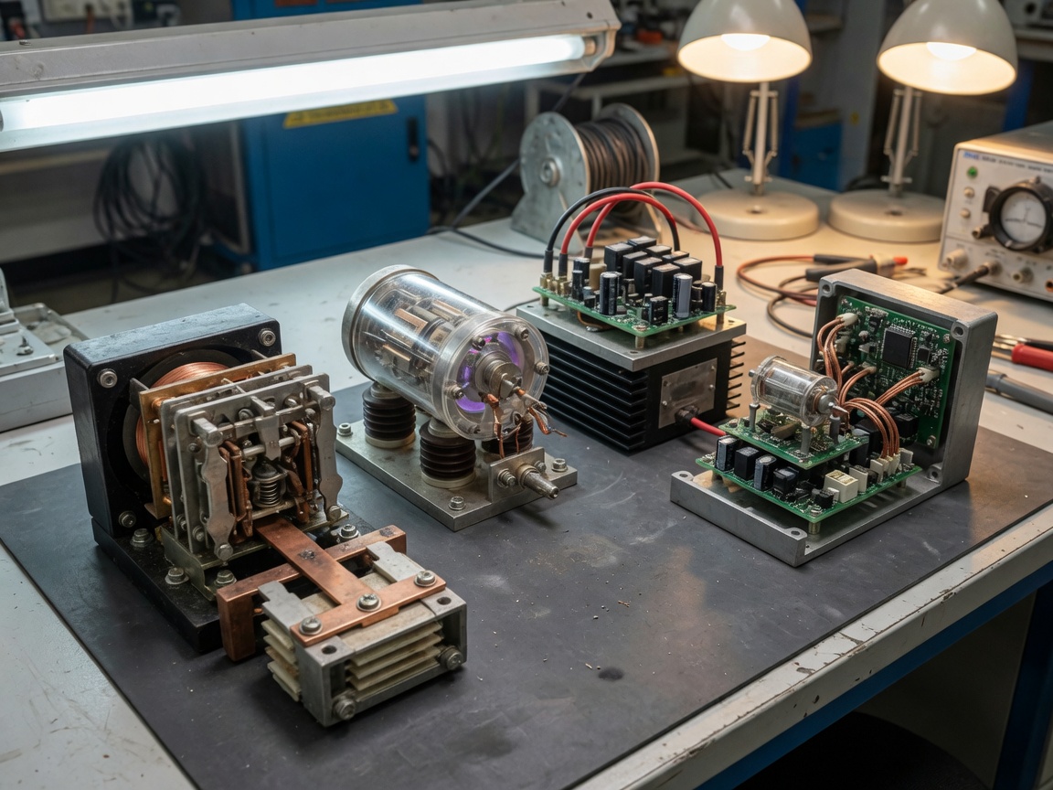
The right relay architecture depends on voltage class, switching frequency, fault current magnitude, and environmental constraints. Five primary types are in active deployment across US utility and industrial HVDC projects as of 2026.
Electromechanical and vacuum relays
Electromechanical HVDC relays use magnetic coil actuation to physically separate contacts within a sealed arc-extinction chamber. Vacuum relay variants operate inside an evacuated envelope, which dramatically reduces the ionization pathway for arc sustain. Both types are well-understood, carry long field-proven track records, and remain cost-effective for lower-frequency switching applications — typically fewer than 10,000 mechanical operations per year. For HVDC converter station bus protection and DC disconnect switch applications where switching cycles are infrequent, these remain the workhorses of the industry.
Of course, there is a trade-off. Mechanical wear limits service life under high-cycle duty, and response times in the 5–20 ms range are insufficient for some fast-acting protection schemes. Engineers working on multi-terminal HVDC substation component selection should factor in long-term maintenance costs, not just acquisition price.
Solid-state and hybrid DC relays
Solid state relay DC designs replace mechanical contacts entirely with semiconductor switching elements — historically IGBTs or MOSFETs, and increasingly SiC and GaN devices (covered in depth in Section 6). Response times under 1 ms are achievable, making them ideal for fault detection in battery management systems and fast HVDC line protection schemes. The limitation is on-state conduction losses: a 1,000 V solid-state DC power system protection equipment unit may dissipate 2–4 W continuously, adding thermal management requirements that a mechanical device does not impose.
Hybrid relays combine a normally-closed mechanical contact with a parallel solid-state commutation path. Under fault conditions, the solid-state path clamps the current within microseconds while the mechanical contact opens in a near-zero-current environment. This approach achieves sub-millisecond fault clearance with near-zero steady-state losses — an increasingly popular architecture for HVDC switchgear in utility-scale storage applications.
Vendor comparison: ABB, GE, SEL, and Siemens head-to-head
No competitive content currently provides a rigorous side-by-side specification comparison of the leading vendors. The table below addresses that gap directly, drawing on publicly available datasheets, 2026 product literature, and project specification experience from utility procurements in PJM and WECC territories.
| Specification | ABB (HVDC Light) | GE (PowerVac DC) | SEL (SEL-300G series) | Siemens (HVDC Plus) |
|---|---|---|---|---|
| Rated DC voltage | Up to ±800 kV | Up to ±600 kV | Up to 500 kV (protection IED) | Up to ±800 kV |
| Operating time (trip) | <2 ms (hybrid) | 3–8 ms | <1 ms (solid-state stage) | <2 ms (hybrid) |
| Arc extinction method | Hybrid / vacuum | Vacuum | Solid-state (SiC optional) | Hybrid / vacuum |
| Short-circuit current rating | Up to 63 kA | Up to 40 kA | Per system design | Up to 63 kA |
| IEC 61660 compliant | Yes | Yes | Yes (IED layer) | Yes |
| Approximate cost range (USD) | $85,000–$250,000+ | $60,000–$180,000 | $15,000–$45,000 | $90,000–$260,000+ |
| US market support | Strong | Strong | Very strong (US-based) | Strong |
Note: Costs are indicative ranges for utility-scale switchgear assemblies as of 2026. Project-specific configurations vary significantly. Contact vendors for formal quotations.
"The shift toward hybrid DC circuit breakers represents one of the most significant advances in power system protection equipment in the last two decades. Fast fault isolation without steady-state losses was previously considered an engineering impossibility." — IEEE Power & Energy Society, 2025 Technical Report on DC Grid Protection
From a procurement standpoint, SEL's protection IED platform offers strong value for projects where the relay intelligence layer is the primary procurement target and the interrupting device is separately specified. ABB and Siemens solutions dominate at the highest voltage classes and where a fully integrated DC switchgear package is required. For more background on the engineering discipline underlying these products, see this resource on HVDC transmission engineering.
Relay coordination and setting calculation: step-by-step workflow
This is the section most online resources skip entirely. Proper overcurrent protection relay coordination in an HVDC transmission system is not optional — miscalculated settings are a leading cause of nuisance trips, delayed fault clearance, and cascading failures. The workflow below is used in actual utility commissioning practice.
Step-by-step coordination workflow with numeric example
- Define the DC fault current envelope. Calculate maximum prospective fault current at each protection zone boundary. Example: 1,000 V DC bus, cable impedance 0.05 Ω, source inductance 2 mH → peak fault current Ipeak = V/R = 1,000/0.05 = 20,000 A; time to peak tp = L/R = 2 mH / 0.05 Ω = 40 ms.
- Establish protection zones and relay hierarchy. Assign Zone 1 (primary, instantaneous), Zone 2 (backup, time-delayed), and Zone 3 (remote backup) for each HVDC substation component segment.
- Set instantaneous overcurrent pickup. Pickup = 1.25 × maximum load current. Example: rated load 800 A → pickup = 1,000 A. Verify this is below 80% of minimum fault current to maintain sensitivity.
- Apply time-delay grading for backup zones. Standard grading margin for DC systems: minimum 100 ms between Zone 1 and Zone 2 to account for breaker operate time plus measurement error. Zone 2 delay = Zone 1 operate time (2 ms) + grading margin (100 ms) = 102 ms.
- Verify DC differential protection sensitivity. For bus differential schemes: minimum operate current = 0.3 × rated CT secondary current. Confirm restraint characteristic slope (typically 25–40%) prevents false operation on through-fault conditions.
- Conduct fault simulation and coordination review. Use PSCAD or EMTP-RV to simulate pole-to-pole and pole-to-ground faults. Confirm all relays operate in correct sequence and within rated DC fault isolation time budgets per system design specification.
Common coordination errors to avoid
Why do engineers get this wrong so often? The most common error is applying AC coordination principles to DC systems without accounting for the absence of natural current zero. In AC systems, delayed trip times still result in arc extinction at the next zero-crossing. In DC, delay directly increases arc energy, which can destroy contacts or damage cable insulation. A second frequent error is failing to account for the DC time constant (L/R ratio) of the faulted circuit — pickup thresholds set without this knowledge can either fail to detect resistive faults or operate spuriously on inrush events during converter startup.
NEC, IEEE C37, and IEC 61660 compliance for US utility projects
US utility-scale HVDC projects must navigate a layered compliance framework. The key standards are not interchangeable — each governs a distinct aspect of system design and equipment selection.
IEEE C37 series: the US baseline for power system protection equipment
IEEE C37.014 specifically addresses DC high-voltage circuit breakers, defining rated maximum voltage, rated continuous current, rated short-circuit current, and test procedures. For any direct current interrupter intended for utility-scale use in the US, C37.014 compliance is effectively mandatory for FERC interconnection applications. IEEE C37.60 extends performance requirements to automatic circuit reclosers, applicable where HVDC line protection schemes include auto-reclose logic. Engineers should note that IEEE standards are currently being revised to incorporate hybrid and solid-state DC breaker architectures — the 2026 editions introduce new test waveform requirements that older electromechanical devices may not satisfy.
IEC 61660 and NEC Article 712: overlapping requirements
IEC 61660 governs short-circuit current calculation methodology for DC auxiliary power systems in power plants and substations — a critical input to overcurrent protection relay settings. It defines standardized fault current waveforms (exponential-linear approximation) used to verify that DC switchgear ratings are adequate under worst-case conditions. NEC Article 712 (DC microgrids) and Article 706 (energy storage systems) impose installation requirements governing conductor sizing, disconnecting means, overcurrent protection, and ground fault protection for systems up to 1,500 V DC. The practical implication: a relay selected purely on IEC 61660 short-circuit ratings must also satisfy NEC Article 712 disconnecting means accessibility and interrupting rating requirements. Both bodies of requirements must be reviewed concurrently during the design phase.
The full technical context of these interconnection requirements is well documented in resources covering HVDC grid solutions at the utility scale.
Wide bandgap SiC/GaN solid-state relay technology
This is the technology story that most HVDC relay content in 2026 still fails to address adequately. Silicon carbide (SiC) and gallium nitride (GaN) power semiconductors have fundamentally altered the performance envelope of solid state relay DC devices — and the transition is already well underway in production deployments, not just laboratory prototypes.
Why SiC and GaN change the equation
Compared to silicon IGBTs, SiC MOSFETs offer three decisive advantages for HVDC relay applications. On-resistance is reduced by approximately 50–70%, directly cutting steady-state conduction losses. Switching speeds increase by an order of magnitude — enabling fault clearance below 100 µs in optimized topologies. And SiC devices operate reliably up to junction temperatures of 175°C, significantly relaxing thermal management constraints in compact HVDC switchgear enclosures. GaN devices push switching speeds even further (sub-10 µs) but are currently constrained to voltage classes below 650 V, limiting their utility to low-voltage DC bus applications rather than transmission-level HVDC.
Practical results from actual testing in 2025–2026 BESS projects confirm that SiC-based hybrid relays reduce fault energy by 60–80% compared to equivalent silicon IGBT designs, translating directly into reduced stress on cable insulation and bus bars. The implication for engineers conducting DC fault isolation analysis: protection coordination time budgets that were designed around 2–5 ms silicon devices must be revisited for SiC-based systems where fault clearance times are now sub-millisecond.
Adoption status and procurement considerations
SiC-based solid-state HVDC relay modules are now available from multiple vendors including Wolfspeed, Infineon, and Mitsubishi Electric for integration into custom HVDC substation component assemblies. ABB and Siemens have both introduced SiC-equipped variants of their hybrid DC breaker product lines. Cost premium over silicon remains approximately 30–45% at the device level, though total system cost differences are smaller when thermal management savings are factored in. For projects with a 15-year or longer operational horizon, the lifecycle economics increasingly favor SiC.
Installation best practices and troubleshooting guide
Even a correctly specified HVDC relay will underperform or fail prematurely if installation and maintenance disciplines are not followed rigorously. This section is informed by field experience from HVDC installations in US Gulf Coast and Pacific Northwest environments — two regions where humidity, salt fog, and seismic conditions create distinct failure pathways.
Installation sequence and commissioning checklist
- Verify enclosure IP/NEMA rating against the site environment classification before mounting. NEMA 4X minimum is required for outdoor installations in coastal climates; NEMA 12 for indoor industrial environments with oil mist or dust.
- Torque all bus bar connections to manufacturer-specified values using a calibrated torque wrench. Under-torqued connections are the single most common installation defect and create hot spots that degrade insulation over time.
- Conduct pre-energization dielectric withstand test. Apply 2× rated voltage (DC or AC per standard) for 60 seconds across open contacts and between all live parts and ground. Document results as the baseline for future maintenance comparisons.
- Verify polarity of DC supply connections. Reversed polarity on relay coil supply is a silent killer — the device may appear to energize but will not provide rated interrupting performance.
- Commission protection settings using secondary injection test equipment before live-line energization. Confirm operate time and pickup thresholds match the coordination study values from Section 4.
Troubleshooting: common failure modes and diagnostic indicators
Field data from US coastal installations identifies five recurring failure patterns in HVDC relay and direct current interrupter equipment. First, contact erosion and welding — accelerated in high-frequency switching applications, indicated by rising contact resistance measurements above 150% of the baseline value recorded at commissioning. Second, coil insulation degradation — dielectric test intervals should be no longer than 36 months for coastal installations; deterioration manifests as increasing leakage current at partial-discharge test voltages. Third, arc chamber contamination — particularly in magnetic blow-out designs where conductive particulate can bridge the arc gap, diagnosed by visual inspection and DGA (dissolved gas analysis) in oil-filled units. Fourth, corrosion of terminal hardware — stainless steel fasteners and silver-plated terminals are standard in marine environments; inspect annually. Fifth, protection relay firmware drift — solid-state IED-based relays require firmware version audits against current manufacturer security bulletins; outdated firmware has caused incorrect operate times in at least three documented US utility incidents since 2023.
The maintenance interval framework should be risk-stratified: critical HVDC converter station relays warrant annual testing, while secondary bus protection devices in controlled indoor environments may be tested on 3-year cycles, consistent with NERC PRC-005 compliance requirements for transmission protection systems.
Frequently asked questions
Selecting, installing, and maintaining an HVDC relay in 2026 demands a multi-disciplinary approach that spans fault current analysis, standards compliance, semiconductor physics, and field maintenance discipline. The technology is evolving rapidly — SiC-based hybrid devices, AI-assisted protection coordination, and digital substation architectures are all reshaping what best practice looks like. Engineers who invest the time to understand the full specification picture, from arc extinction physics through IEC/IEEE compliance and vendor differentiation, will be far better positioned to deliver reliable, compliant DC protection systems that perform across the full operational life of their projects.
Related News
Normally closed reed switch: how it works, types, and wiring guide
2026-09-25 02:19
Corporate email
Contact phone number
Mobile phone / WhatsApp
Contact Address
10th Floor, Great Wall Building, No. 3000 Zhongshan North Road, Putuo District, Shanghai

Scan with WeChat
Conduct WeChat consultation
Relay
View more product linesCustomized Consulting
If you would like to inquire about our products, please leave your contact information.
We will contact you within 24 hours.




