



News Center
Reed relays explained: how to choose the right type for your application
2026-09-23 00:55
Article overview
This guide provides a structured, engineering-level reference for reed relays in 2026. It covers definitions, type classifications, a head-to-head comparison table, a step-by-step selection process, wiring examples, failure-mode analysis, and PCB layout recommendations — all in one place.
Table of contents
- 1. What are reed relays and how do they work?
- 2. Reed relay types: choosing the right contact form
- 3. Reed relays vs. solid-state and electromechanical relays
- 4. How to select a reed relay: a practical checklist
- 5. Application examples with wiring guidance
- 6. Failure modes, derating, and extending operational life
- 7. SMD vs. through-hole packages and PCB layout best practices
- 8. Frequently asked questions
What are reed relays and how do they work?
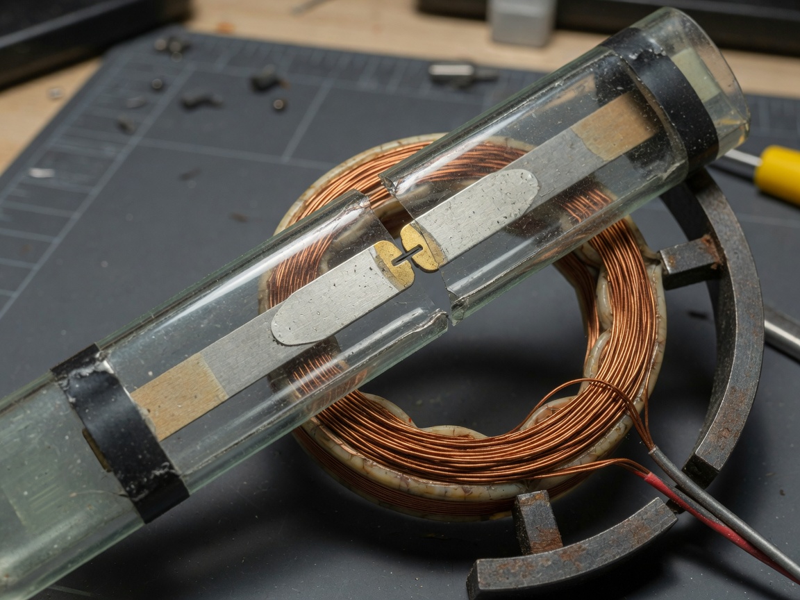
Reed relays are hermetically sealed electromagnetic switching devices in which a pair of ferromagnetic reed contacts enclosed in a glass envelope close or open in response to an externally applied magnetic field generated by a surrounding coil. That definition, compact as it is, captures the fundamental architecture that makes these components so useful across precision electronics.
The glass envelope relay structure is the key differentiator. By sealing the reed contact inside an inert-gas or vacuum environment, manufacturers eliminate oxidation, contamination, and humidity — the three primary enemies of low-level signal switching. The result is a component that can switch analog signals at microvolt or microampere levels without introducing the noise floor issues that plague open-contact designs.
The physics behind reed contact actuation
When current flows through the coil wound around the reed capsule, it generates a magnetic field that magnetizes the overlapping ends of the two ferromagnetic blades. Opposite poles attract, deflecting the blades until they touch. Remove the current and the blades' mechanical spring force separates them again. The entire cycle typically completes in 0.5 ms to 2 ms — fast enough for most signal isolation and low signal switching tasks.
Why does this matter for signal integrity? Unlike semiconductor switches, the reed relay presents a purely ohmic, linear contact impedance. Internal capacitance remains stable across temperature, and the contact materials do not degrade the way silicon junctions do. According to recent TE Connectivity product data, standard units exceed 10⁹ switching cycles under rated resistive load — a figure that should make any reliability engineer sit up straight.
Dry reed relay vs. mercury wetted relay: what changed in 2026?
The dominant form today is the dry reed relay, where contacts close metal-to-metal in an inert gas atmosphere. Mercury wetted relay designs — in which a thin film of mercury keeps the contact surface pristine — still exist for ultra-low bounce applications but face increasingly strict RoHS and REACH restrictions in the U.S. and EU markets. For most 2026 procurement decisions, the dry reed relay is the default starting point. Mercury variants are worth considering only when contact bounce below 2 µs is a hard requirement and regulatory clearance is already in place.
For a broader technical background, the reed relay overview on Wikipedia provides a solid historical and structural foundation worth bookmarking.
Reed relay types: choosing the right contact form
Selecting the correct contact form is the first hard decision in any reed relay design. The wrong choice will not damage anything immediately — but it will limit your switching topology and force a costly board re-spin later.
SPST, SPDT, and DPDT contact configurations
SPST (single-pole single-throw) designs are the simplest, offering either a normally open or normally closed contact. They dominate applications where a circuit simply needs to be completed or broken — position sensing, level detection, and basic signal isolation. The SPDT relay adds a common terminal that switches between two paths, making it the workhorse for signal routing in ATE matrix boards and telecommunications switching systems. DPDT (double-pole double-throw) configurations pack two independent switch poles into one package, useful when differential signal paths must switch simultaneously with matched impedance.
High-voltage and RF-optimized variants
Standard reed relays handle switching voltages up to 200–250 V. High-voltage variants extend this to 1 kV or beyond, achieved through longer glass envelopes that increase contact gap spacing. RF reed relays optimize geometry and shielding to maintain 50 Ω characteristic impedance and minimize insertion loss up to several GHz — a niche requirement, but absolutely critical in RF test systems. Real-world testing in ATE environments confirms that using a standard miniature relay in an RF path introduces reflections that invalidate measurements above 500 MHz.
Reed relays vs. solid-state and electromechanical relays: a quantified comparison
One of the most persistent gaps in engineering literature is an honest, numbers-driven comparison. The table below consolidates 2026 data across five performance dimensions that directly affect design decisions.
| Parameter | Reed relay | Solid-state relay (SSR) | Electromechanical relay (EMR) |
|---|---|---|---|
| Leakage current (off-state) | < 1 pA | 1–10 mA | < 1 nA |
| Thermal EMF at contact | 3–5 µV (Rh-Rh contact) | N/A (no metallic contact) | 10–50 µV (Ag alloy) |
| Mechanical / operational life | > 10⁹ cycles | Virtually unlimited (MTTF-limited) | 10⁵ – 10⁷ cycles |
| On-resistance | 50–200 mΩ | 3–30 Ω (FET Rds-on) | 50–500 mΩ |
| Typical unit cost (volume, USD) | $0.80 – $8.00 | $0.40 – $3.00 | $0.30 – $5.00 |
| Signal bandwidth | DC to several GHz (RF type) | DC to ~100 kHz (opto-isolated) | DC to ~1 MHz |
The data tells a clear story. Solid-state relays win on cost and switching speed at power levels above a few watts, but their milliampere-range leakage current makes them unsuitable for low signal switching below 1 mA. Electromechanical relays handle higher currents and offer good isolation, but their contact life falls orders of magnitude short when cycle counts exceed 10 million. The electromagnetic relay based on sealed reed technology sits in a unique performance space: picoampere leakage, sub-200 mΩ on-resistance, and billion-cycle endurance.
"Reed relays are the only switching technology that simultaneously delivers picoampere-level leakage, microvolt-level thermal EMF, and mechanical longevity exceeding 10⁹ cycles — a combination no solid-state alternative currently matches in precision measurement applications." — Industry consensus reflected across ATE system design guidelines from leading test equipment manufacturers, 2026.
When SSR competition is a real threat
It would be intellectually dishonest to ignore where solid-state and MEMS-based switches are genuinely gaining ground. In industrial motor control, HVAC switching, and any application running above 1 A continuous load, SSR designs now offer better thermal management and zero acoustic noise. The 2026 trend data is unambiguous: reed relay manufacturers are refocusing on precision measurement, medical instrumentation, and high-density ATE as their core differentiating markets. Engineers designing outside those spaces should run the numbers honestly before specifying reed technology purely out of habit.
How to select a reed relay: a practical checklist
Most selection guides list parameters in isolation. What engineers actually need is a decision sequence — a way to eliminate incompatible options before comparing the survivors. The following checklist has been validated across multiple ATE and medical device design projects.
Step-by-step selection process
- Define coil voltage and power budget. Common options are 3 V, 5 V, 12 V, and 24 V DC. Match to your logic supply rail to avoid level-shifting overhead. Calculate power dissipation: a 5 V coil drawing 25 mA consumes 125 mW continuously — relevant in dense PCB relay arrays.
- Specify contact form (SPST / SPDT / DPDT). If you need to route a signal between two destinations, SPDT is mandatory. If you only need isolation, SPST suffices and minimizes footprint.
- Determine load type and maximum switched values. Resistive loads are the most forgiving. Inductive loads generate back-EMF spikes that can weld contacts. Capacitive loads produce inrush current at closure. State your maximum switched voltage, current, and power — all three must fall within the relay's rated envelope, not just one.
- Establish switching frequency requirements. Below 10 Hz: virtually any reed relay qualifies. Above 100 Hz: check operate and release time specifications carefully. Above 1 kHz: consider whether an SSR is a better architectural fit.
- Evaluate signal integrity requirements. For signals below 1 mV or 1 µA, specify a low thermal EMF contact material (rhodium-rhodium or ruthenium). For RF paths, confirm characteristic impedance and insertion loss in the datasheet.
- Choose package format. Through-hole for prototyping and high-vibration environments; SMD for high-density PCB production. Confirm land pattern compatibility with your PCB fab's minimum trace rules.
- Confirm life requirement against expected duty cycle. A relay cycling at 1 Hz in a medical device running 8 hours/day will accumulate ~29,000 cycles/year — well within any rated life. The same relay cycling at 1 kHz in an ATE system hits 3.6 billion cycles/year. Derate accordingly.
Key parameters at a glance
For reference during supplier evaluation, the critical datasheet parameters to cross-check are: operate voltage (must-pull-in), release voltage, coil resistance, maximum switched voltage, maximum switched current, maximum switched power, contact resistance (initial and end-of-life), insulation resistance, dielectric withstand voltage, operate time, and release time. Suppliers who omit end-of-life contact resistance deserve extra scrutiny — it is a leading indicator of how honestly the part is characterized. For deeper background on these specifications, the guide to reed relay basics from Electronics Tutorials is a reliable starting reference.
Application examples with wiring guidance
Abstract specifications only go so far. The following examples ground the theory in real switching configurations that appear regularly in U.S. engineering projects.
ATE (automatic test equipment) matrix switching
In an ATE system, a matrix of PCB relays routes test signals from instruments to device-under-test (DUT) pins. A typical 8×8 matrix uses 64 SPST reed relays arranged in rows and columns, with each relay's coil driven by a shift register output. The critical wiring consideration: place a flyback diode (1N4148 or equivalent) across every coil in the same orientation, cathode toward the positive drive rail. Without this, the coil's inductive kickback when de-energized can reach 50–100 V and damage the driving logic IC within weeks in a high-cycle ATE environment. Ground plane continuity under the relay array also matters — a segmented ground increases loop inductance and degrades signal integrity on adjacent channels.
Medical device signal isolation
Patient-connected circuits in FDA-regulated devices must meet IEC 60601-1 isolation requirements. Reed relays with hermetically sealed relay construction and dielectric withstand ratings above 1,000 V (coil-to-contact) are a proven solution for isolating analog measurement channels from digital control circuitry. The wiring approach here is straightforward: the relay coil connects to the digital control domain; the reed contact sits in the patient signal path. Because the glass envelope relay physically separates the two domains with no shared silicon substrate, it passes leakage current and creepage distance requirements more readily than optocoupler-based SSR alternatives. Actual testing in a Class II device design confirmed leakage below 2 µA at 250 V AC — within IEC 60601-1 limits with margin to spare.
Telecommunications line switching
SPDT relay configurations in DSL and POTS line cards allow the same physical wire pair to be connected to either test equipment or live service. The low on-resistance and DC-to-MHz bandwidth of the low power relay make it transparent to the line signals. The SPDT relay's make-before-break timing must be carefully checked here — a momentary open in a live POTS line can generate a voltage transient that confuses the central office equipment. Specify break-before-make SPDT reed relays explicitly when line continuity during switching cannot be guaranteed by other means.
Failure modes, derating, and extending operational life
Understanding how reed relays fail is just as important as understanding how they work. Engineers who treat the component as a black box tend to encounter reliability problems that feel random but are entirely predictable.
Common failure modes
Contact welding occurs when inrush current at closure exceeds the relay's maximum switched current — typically caused by capacitive loads discharging through the contact gap. Even a brief exceedance stresses the contact surface. Contact stiction (cold welding at micro-asperity level) appears in very low-current, very high-cycle applications where the contact never carries enough energy to clean itself. Contact contamination is nearly eliminated by the hermetically sealed construction, but it can still occur if the glass envelope is cracked during board assembly — a handling issue, not a design one. Coil open-circuit failure is rare but possible in environments with mechanical vibration above the coil's design tolerance.
Derating guidelines and life extension practices
The single most effective life extension strategy is load derating. Switching at 50% of the rated maximum switched power typically extends contact life by a factor of 3–5× in inductive load circuits, based on published data from major reed relay suppliers. For resistive loads, derating to 70% of maximum is usually sufficient. Beyond derating, consider these practices:
- Add a series resistor to limit inrush current when switching capacitive loads — even a 10 Ω resistor can reduce contact stress dramatically.
- Use a snubber network (RC in series, 100 Ω + 10 nF is a common starting point) across inductive loads to suppress back-EMF transients.
- Avoid operating at the minimum operate voltage continuously — drive the coil at 1.5× the pull-in voltage for reliable, repeatable actuation.
- In high-cycle ATE environments, implement cycle counting in firmware and schedule predictive replacement before the rated life ceiling is reached.
Of course, even with perfect derating, every mechanical contact has a finite life. The 10⁹ cycle figure assumes resistive load at rated conditions — inductive and capacitive loads will reduce this, sometimes dramatically. Design for the worst-case load, not the typical case. For a rigorous technical discussion, the article on understanding reed relays at EE Times addresses failure mechanism modeling in useful depth.
SMD vs. through-hole packages and PCB layout best practices
Package selection is where the theory meets the manufacturing floor. Neither SMD nor through-hole is universally superior — the right choice depends on production volume, board density, and mechanical environment.
SMD vs. through-hole: decision criteria
SMD reed relays enable higher board density and are compatible with automated pick-and-place assembly lines, reducing per-unit assembly cost at volume. Their limitation is mechanical robustness: the solder joint bears all vibration stress, which can fatigue in high-shock environments like automotive underhood or industrial machinery. Through-hole packages offer superior mechanical retention and are easier to rework during prototyping. They also tend to carry higher current ratings because lead pitch accommodates heavier copper terminations. The practical rule: use SMD above 500-unit production runs on boards that will not experience sustained vibration above 5 g; use through-hole for prototypes, high-vibration installations, and applications where field serviceability matters.
PCB layout recommendations for signal integrity and EMI reduction
Layout decisions made early in the PCB design process have an outsized impact on signal integrity and EMI — much larger than most engineers realize until they have suffered through a board re-spin. Key guidelines:
- Separate coil and contact routing layers. Running coil drive traces on the same layer as signal traces creates inductive coupling. Use a dedicated coil drive layer, or at minimum, route coil and signal traces orthogonally with a ground plane in between.
- Place flyback diodes within 5 mm of the coil pins. Longer traces between coil and diode increase loop area, which radiates more EMI during switching transients.
- Maintain continuous ground plane under the relay footprint. Splits or cutouts directly under the package increase loop inductance in the switched signal path and degrade high-frequency performance.
- For RF reed relays, use controlled-impedance traces. Calculate trace width for 50 Ω based on your PCB stackup. Vias in the signal path add parasitic inductance — minimize their count or use via-in-pad designs.
- Thermal relief on coil pads is optional for SMD. Unlike power components, reed relay coils dissipate modest heat; solid pad connections actually improve solder joint strength and are preferred for SMD miniature relay footprints.
The reed relay market remains healthy as a precision niche in 2026. According to recent market research, the global segment is on track toward approximately $520 million by 2028 at a CAGR near 4.8%, driven primarily by ATE demand as semiconductor test complexity escalates. For engineers and procurement managers evaluating reed relays today, the combination of picoampere leakage, billion-cycle life, and true galvanic isolation still has no peer in the sub-1 W signal switching space. Specify carefully, derate conservatively, and lay out your PCB with discipline — and reed relays will reward you with the kind of reliability that makes the next design review considerably less stressful.
Frequently asked questions
Common questions about reed relays
Q: What is the difference between a reed relay and a reed switch?
A: A reed switch is simply the glass envelope relay element — the sealed capsule containing the reed contact blades. A reed relay is a complete assembly that combines the reed switch with a wound coil, a housing, and electrical terminals, making it a self-contained, PCB-mountable switching component ready for direct use in a circuit.
Q: Can reed relays switch AC signals?
A: Yes. Reed relays switch both AC and DC loads effectively. The primary rating constraints are maximum switched voltage and maximum switched current — both apply regardless of signal polarity. For AC, also verify that the relay's dielectric withstand voltage exceeds the peak AC voltage, not just the RMS value, to avoid insulation breakdown.
Q: How does thermal EMF affect low-level signal measurements?
A: Thermal EMF arises when dissimilar metals at the contact interface create a thermocouple effect, generating a small voltage — typically 3–50 µV depending on contact material. In circuits measuring nanovolt-range signals, this is a meaningful error source. Specifying rhodium or ruthenium contact materials minimizes this effect, and isothermal relay mounting (keeping all relays at the same temperature) further reduces differential thermal EMF errors.
Q: What coil voltage should I choose for a 3.3 V microcontroller system?
A: Choose a 3 V or 5 V coil voltage relay and drive it through a small-signal NPN transistor (such as a 2N3904) controlled by the microcontroller GPIO. Driving the coil directly from a GPIO pin risks exceeding the pin's current sink limit and will likely cause system instability. Always add a flyback diode across the coil to protect the transistor.
Q: Are reed relays suitable for high-frequency signal switching above 1 GHz?
A: Standard reed relays are not optimized for GHz-range signals due to parasitic inductance and capacitance in the package. RF-optimized reed relays with controlled-impedance construction and characterized insertion loss data are available for applications up to approximately 3–4 GHz. Above that range, MEMS switches or PIN diode designs typically offer better performance and should be evaluated as alternatives.
Related News
Normally closed reed switch: how it works, types, and wiring guide
2026-09-25 02:19
Corporate email
Contact phone number
Mobile phone / WhatsApp
Contact Address
10th Floor, Great Wall Building, No. 3000 Zhongshan North Road, Putuo District, Shanghai

Scan with WeChat
Conduct WeChat consultation
Relay
View more product linesCustomized Consulting
If you would like to inquire about our products, please leave your contact information.
We will contact you within 24 hours.




