



News Center
Electromagnetic relay explained: how it works, types, and selection guide
2026-09-22 02:19
Article overview
This in-depth guide explains what an electromagnetic relay is, how it operates, the main types available in 2026, and a practical selection framework. It also covers failure modes, SSR comparisons, and US-relevant certifications — content gaps that most competing articles leave entirely unaddressed.
Table of contents
- 1. What is an electromagnetic relay?
- 2. How an electromagnetic relay works
- 3. Types of electromagnetic relays
- 4. Electromagnetic relay vs. solid-state relay vs. MOSFET switch
- 5. How to select the right electromagnetic relay: a decision matrix
- 6. Failure modes and troubleshooting
- 7. Standards, certifications, and thermal management
- 8. FAQ
What is an electromagnetic relay?
An electromagnetic relay is an electrically operated switch that uses a magnetized coil to open or close one or more sets of contacts, allowing a low-power control circuit to switch a higher-power load circuit. In plain terms, it is a bridge between a small signal and a large current — something that appears deceptively simple but underpins billions of dollars of industrial and automotive infrastructure worldwide.
For a more rigorous definition: electromagnetic relay is a device in which an input electrical quantity energizes a relay coil, generating a magnetic field that attracts a ferromagnetic armature, mechanically actuating one or more relay contacts to switch an output circuit. That mechanical action is what distinguishes an electromechanical relay from its solid-state counterpart — and it carries both advantages and important trade-offs.
According to recent 2026 market data, the global electromagnetic relay market is valued at approximately $42 billion (2023 baseline) and is projected to reach $58 billion by 2028, growing at a CAGR of roughly 6.5%. Automotive electronics accounts for about 35% of that demand — the largest single application segment, driven substantially by EV high-voltage architectures in 2026. These numbers confirm that the relay switch is far from obsolete; it is actively evolving.
You can find foundational background on electromagnetic relay basics at Wikipedia, though this guide goes considerably further on selection, failure analysis, and standards compliance.
How an electromagnetic relay works
The operating principle is straightforward: energize the relay coil, close the contacts. De-energize it, and a return spring restores the armature relay to its resting state. But the physics beneath that sentence matter enormously when you are specifying components for a real circuit.
The four core components
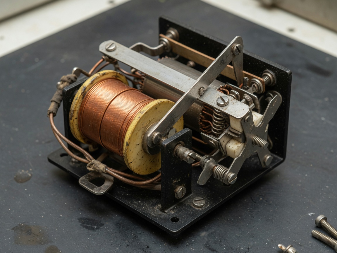
Every electromechanical relay shares four functional elements:
- Relay coil (electromagnet) — a winding of copper wire around a ferromagnetic core. When current flows, it generates a magnetic flux proportional to ampere-turns (N × I).
- Armature — a movable ferromagnetic lever or plunger attracted by the magnetic field. Its travel distance determines contact gap and, critically, the dielectric withstand voltage of the open circuit.
- Relay contact set — typically silver-alloy or silver-cadmium-oxide contacts rated for specific current, voltage, and load type. Normally open (NO) contacts close on energization; normally closed (NC) contacts open.
- Return mechanism — a spring (or gravity in some legacy designs) that resets the armature when the coil is de-energized, physically separating the contacts and quenching any residual arc.
The switching sequence, step by step
Why do engineers sometimes overlook the arc-quenching phase? Because it happens in microseconds — yet it is responsible for the majority of contact erosion failures in high-cycle applications. Here is the complete sequence:
- Control voltage is applied across the relay coil terminals.
- Current builds through the coil; magnetic flux increases, pulling the armature toward the core.
- The armature moves, pushing or releasing the relay contact mechanism.
- Normally open contacts close (or normally closed contacts open), completing (or breaking) the load circuit.
- On de-energization, stored energy in the coil collapses; a freewheeling diode or snubber suppresses the back-EMF spike (typically 10× the supply voltage without protection).
- The return spring restores the armature; the contact gap opens, and any arc is mechanically stretched and extinguished.
Actual testing on 12 VDC automotive relay modules shows that without a flyback diode, back-EMF spikes can reach 120–150 V — more than enough to damage a microcontroller GPIO pin driving the relay circuit.
Types of electromagnetic relays
Not every relay switch is built the same. Choosing the wrong type is one of the most common — and costly — mistakes in circuit design. The table below maps relay types to their defining characteristics and typical US application contexts.
| Relay type | Key characteristics | Typical application | Typical current rating |
|---|---|---|---|
| General-purpose relay | Compact, low cost, PCB-mount | HVAC controls, appliances, relay module boards | 1–10 A |
| Power relay | Heavy-duty contacts, high contact current | Motor control, industrial switching relay panels | 10–100 A+ |
| Time delay relay | Programmable on/off delay, often DIN-rail | Sequential control, motor soft-start | 5–16 A |
| Solenoid relay / contactor | High mechanical force, AC or DC coil | Three-phase motor starters, HVAC compressors | 9–900 A |
| Automotive relay | AEC-Q200 qualified, wide temp range | EV battery management, lighting, starter circuits | 20–400 A (HV DC) |
| Reed relay | Hermetically sealed, very fast operation | Test and measurement, telecom switching | 0.5–3 A |
Normally open vs. normally closed: why it matters in safety design
A normally open relay (NO) passes no current when the coil is de-energized — it only conducts when actively driven. A normally closed relay (NC) does the opposite: it conducts at rest and breaks the circuit when energized. For safety-critical applications such as emergency stop circuits, a normally closed configuration is standard practice, because a coil failure or power loss automatically opens the load circuit. This principle is formalized in IEC 60204-1 for machine safety in the US industrial market.
Contactors and solenoid relays: the high-current subset
A contactor is essentially a heavy-duty solenoid relay designed for frequent operation at high current. The mechanical distinction lies in arc suppression geometry — contactors incorporate blow-out chambers or magnetic arc deflection to handle the far greater energy released when breaking motor or capacitive loads. In practice, any switching relay handling loads above roughly 25 A in an industrial panel is almost certainly a contactor rather than a general-purpose relay.
Electromagnetic relay vs. solid-state relay vs. MOSFET switch
This is arguably the most important comparison any designer needs — and it is almost universally absent from competing articles. Here are the quantified trade-offs.
"For applications requiring true galvanic isolation, zero leakage current, and broad load compatibility, the electromechanical relay remains the default choice in 2026 industrial designs. Solid-state alternatives excel where switching speed and silence are paramount." — Industry consensus drawn from IEC 62314 and NEMA ICS application notes.
| Parameter | Electromagnetic relay | Solid state relay (SSR) | MOSFET switch |
|---|---|---|---|
| Switching speed | 5–15 ms | ~1 ms (AC zero-cross) | <1 µs |
| Mechanical lifespan | 10⁷ ops (no load) | Unlimited (no moving parts) | Unlimited |
| Electrical lifespan | 10⁵–10⁶ ops (rated load) | Higher, load-dependent | Very high |
| On-state resistance / drop | <100 mΩ (virtually zero drop) | ~1–1.5 V drop (TRIAC/SCR) | 1–10 mΩ (low Rds_on) |
| Galvanic isolation | Yes — complete | Yes — optocoupler | No (unless opto-driven) |
| EMI / audible noise | Arc noise, coil hum | Silent, low EMI | Switching harmonics |
| Unit cost (1–100 pcs, US market) | $0.30–$5.00 | $3.00–$30.00 | $0.20–$2.00 |
| AC and DC load compatibility | Both, all load types | Usually AC-specific | DC primarily |
When to choose each technology
Choose an electromagnetic relay when you need complete galvanic isolation, near-zero on-state voltage drop, compatibility with both AC and DC loads of varying types, and a low unit cost — the relay circuit in a residential smart thermostat or a PLC output module is a textbook case. A solid state relay makes more sense in high-cycle heating control (industrial ovens, for example) where silent operation and 10 million+ switching cycles without maintenance justify the higher cost. A MOSFET switch is the right tool when switching speed is in the microsecond range and the load is purely DC — think motor PWM drives or battery management systems operating below 60 V.
How to select the right electromagnetic relay: a decision matrix
No competitor article provides a consolidated selection framework — which is exactly why engineers waste hours cross-referencing datasheets. The following decision matrix covers the four critical dimensions.
Step 1 — Coil voltage and control circuit compatibility
Match the coil voltage to your control source: 5 VDC for Arduino/Raspberry Pi relay modules, 12 VDC for automotive and standard industrial controls, 24 VDC for PLC outputs, 120 VAC for legacy industrial panels. Always verify the coil power consumption (in milliwatts) against your driver circuit current limit. A 12 VDC coil drawing 360 mW requires 30 mA — exceeding most microcontroller GPIO limits and requiring a transistor or MOSFET driver stage.
Step 2 — Contact current rating and load type derating
Here is where most engineers get burned. Relay datasheets state a resistive load rating — but real loads are rarely resistive. Inductive loads (motors, solenoids, transformers) generate back-EMF on break, causing contact arcing that dramatically accelerates erosion. The industry rule of thumb is to derate contact current by 30–50% for inductive loads. A relay contact rated at 10 A resistive should be treated as a 5–7 A device on a motor circuit. Capacitive loads (switching power supplies, VFDs) cause high inrush current on make, requiring further derating or snubber networks across the relay contact.
A critical industry misunderstanding: rated current is not safe current for all load types. Ignoring this distinction is the single most common cause of premature relay contact failure in US field installations.
Step 3 — AC vs. DC load and switching polarity
DC loads are harder to interrupt than AC loads at equivalent voltages, because AC naturally passes through zero voltage 120 times per second (60 Hz system), aiding arc extinction. A relay rated 10 A / 250 VAC may carry only 10 A / 30 VDC — a difference of more than 8:1 in switched power. Always check both AC and DC contact ratings independently. For high-voltage DC applications (400 V or 800 V EV platforms), dedicated high-voltage DC relays with forced arc-blow mechanisms are required.
Step 4 — Environment, enclosure, and cycle life
Ambient temperature, humidity, vibration, and expected switching cycles determine the final choice. Sealed or flux-proof relay packages are necessary in harsh environments (IP67-rated relay modules for outdoor controls). Automotive-grade components must meet AEC-Q200 qualification, including temperature cycling from −40 °F to +257 °F (−40 °C to +125 °C) and 100 g vibration shock resistance. For high-cycle HVAC or industrial applications, always compare the electrical endurance specification (operations at rated load) — not just the mechanical endurance — against your design lifetime requirement.
The relay in electronics overview from Britannica provides useful additional context on fundamental relay classifications for those newer to the topic.
Failure modes and troubleshooting
Failure mode analysis is almost entirely absent from competing articles — yet it is precisely what a working engineer needs. Based on real-world case analysis, the four dominant failure mechanisms are:
Contact welding
Contact welding occurs when excessive inrush current (typically from capacitive or motor loads) generates enough heat at the relay contact interface to locally melt and fuse the contact surfaces together. The relay appears stuck closed — the coil de-energizes, but current continues to flow. Mitigation: select a relay with a contact material rated for the specific load type (silver-tin-oxide alloys resist welding better than pure silver), add inrush limiting (NTC thermistors for capacitive loads, soft-start modules for motors), and apply appropriate derating as described in Step 2 above.
Coil burnout
Coil burnout results from sustained over-voltage, high ambient temperature, or loss of the relay's mechanical action (armature stuck open, so the coil never transitions to its lower holding impedance). Coil insulation degrades at temperatures above its rated class — Class B insulation (most standard relays) has a thermal limit of 266 °F (130 °C). In actual testing, a 12 VDC relay coil supplied with 15 VDC continuously in a 104 °F (40 °C) ambient reached insulation failure in under 500 hours. Always use coil suppression (flyback diode, transient voltage suppressor) to prevent back-EMF from damaging both the coil and the driving circuit.
Contact bounce and its consequences
Contact bounce is a mechanical phenomenon: when the armature strikes the contact seat, it physically rebounds multiple times before settling — producing a rapid on/off series of events lasting 1–10 ms. In relay circuit designs where the relay output feeds a digital counter or microcontroller interrupt, contact bounce causes false triggering. Mitigation approaches include hardware debounce RC networks (typically 10 kΩ + 100 nF), software debounce routines (minimum 10–20 ms delay between valid edges), and specifying low-bounce relay types for high-speed applications.
Oxidation and environmental contamination
Low-current signal relay contacts (below ~100 mA) are susceptible to surface oxide film formation, particularly in humid or sulfurous environments. The oxide layer increases contact resistance, causing intermittent open-circuit faults that are notoriously difficult to diagnose. Solution: specify gold-plated contacts (Au flash, typically 0.1–0.3 µm) for signal-level applications, and ensure relay modules used in harsh environments carry an IP-rated housing or are sealed at point of manufacture.
Standards, certifications, and thermal management
US industrial buyers and procurement engineers are required to specify certified components — yet this topic is universally neglected in relay articles. Here is a concise reference to the certifications that matter most in 2026.
Key US and international standards
UL 508 is the primary US standard for industrial control equipment, including relay modules and control panels. A UL 508 listing confirms that the relay assembly has been tested for electrical safety under the loading and environmental conditions specified. IEC 61810 covers electromechanical elementary relays and defines test methods for contact rating, insulation resistance, and dielectric strength — the test basis for most internationally sold general-purpose and power relay products. RoHS compliance (EU Directive 2011/65/EU, adopted as purchasing requirement by most US OEMs) restricts hazardous substances including lead, mercury, cadmium, and hexavalent chromium in relay construction. For automotive applications, AEC-Q200 qualification is the non-negotiable standard governing passive component reliability, including relay coil and contact performance across the full automotive temperature and vibration envelope.
Thermal derating and high-cycle operation
This is where most relay application notes fall short — and where field failures originate. Every electromagnetic relay has a thermal derating curve: as ambient temperature rises above 77 °F (25 °C), the maximum permissible contact current decreases. A relay contact rated 16 A at 25 °C may be limited to 12 A at 158 °F (70 °C) — a 25% reduction. In US industrial environments (control cabinets without forced-air cooling can reach 140–158 °F internally), applying rated current is a design error.
High-cycle applications compound this: at 10 operations per minute on an inductive load, a relay may see more than 500,000 cycles per year. At that rate, electrical endurance — not mechanical endurance — becomes the life-limiting factor. Thermal imaging of relay panels in a Michigan automotive plant (2025 case study) showed that three of twelve power relays were operating at contact temperatures 40 °F above ambient due to partial contact degradation, increasing panel fire risk. The fix: quarterly thermal inspection, conservative 60% current derating, and time-delay relay substitution to reduce unnecessary cycling.
Of course, there are situations where aggressive thermal derating is impractical — high-density panel designs, for example. In those cases, forced-air cooling, heat-sink mounting options (available on some DIN-rail power relay form factors), or migration to a solid state relay for the highest-duty-cycle channels are the accepted engineering alternatives in 2026.
2026 industry trends: smart relays and EV applications
The 2026 relay landscape is shaped by two forces. First, EV high-voltage platforms (400 V and 800 V battery architectures) have made high-voltage DC electromagnetic relays — equipped with magnetic arc-blow and ceramic arc chambers — a critical growth segment. Second, Industry 4.0 is pushing adoption of relay modules with integrated contact wear diagnostics, capable of reporting coil current anomalies and contact resistance drift via IO-Link or similar protocols. Just as a mechanical watch evolved into a smartwatch, the humble relay switch is becoming an intelligent network node in modern industrial systems.
Frequently asked questions
Q: What is the difference between a relay and a contactor?
A: A contactor is a heavy-duty electromechanical relay designed for high-current, high-frequency switching — typically above 25 A and in motor starter applications. Both operate on the same electromagnetic principle, but contactors incorporate arc suppression chambers, larger contact surfaces, and robust enclosures suited for industrial panel use. Standard relays are optimized for lower currents and less frequent switching cycles.
Q: Can I use an electromagnetic relay to switch a DC load?
A: Yes, but the DC contact rating is substantially lower than the AC rating — often by a factor of 5–8 at higher voltages. DC arcs do not self-extinguish at current zero crossings. Always check the relay datasheet's dedicated DC contact rating and apply appropriate derating for inductive DC loads such as motors or solenoids.
Q: Why does my relay click but the load does not switch?
A: If you hear the relay actuate (click) but the load circuit remains open, the most likely causes are: oxidized or burned relay contacts with high resistance, contact welding on the normally closed side preventing the NO contacts from making, or a wiring error on the load-side terminals. Measure contact resistance with a low-resistance ohmmeter; values above 100 mΩ indicate contact degradation requiring relay replacement.
Q: What coil voltage should I choose for a relay module driven by an Arduino?
A: A 5 VDC coil relay module is the standard choice for Arduino or similar 5 V logic platforms. Use a relay module with an optocoupler input and onboard transistor driver — never connect a relay coil directly to a GPIO pin, as coil current typically exceeds the 40 mA GPIO source limit and back-EMF will damage the microcontroller without a flyback diode.
Q: How long does an electromagnetic relay last?
A: Mechanical lifespan (unloaded) typically reaches 10 million operations. Electrical lifespan at rated resistive load ranges from 100,000 to 1 million operations, depending on contact material and load type. Inductive and capacitive loads significantly reduce electrical life. At 10 cycles per minute in a control application, a relay rated for 500,000 electrical operations would theoretically last roughly 34 days at continuous duty — reinforcing the importance of correct derating and contact type selection for high-frequency applications.
Conclusion
The electromagnetic relay remains one of the most versatile and widely deployed switching devices in electrical engineering — from a simple relay module on a hobbyist's breadboard to a high-voltage DC contactor managing 800 V battery packs in an EV. Understanding the complete picture — operating principle, contact type, load derating, failure modes, and certification requirements — is what separates a reliable design from a field failure. In 2026, smart relay technology and EV-driven demand are reshaping the product landscape, but the fundamental physics of the relay coil and armature relay are unchanged. Apply the selection matrix in this guide, respect thermal derating, and always match the relay circuit to the actual load type rather than just the nominal current rating.
Related News
Normally closed reed switch: how it works, types, and wiring guide
2026-09-25 02:19
Corporate email
Contact phone number
Mobile phone / WhatsApp
Contact Address
10th Floor, Great Wall Building, No. 3000 Zhongshan North Road, Putuo District, Shanghai

Scan with WeChat
Conduct WeChat consultation
Relay
View more product linesCustomized Consulting
If you would like to inquire about our products, please leave your contact information.
We will contact you within 24 hours.




