



News Center
Reed switch sensor explained: how it works, types, and selection guide
2026-09-22 00:59
Article overview
This guide explains reed switch sensor technology at the engineering level — covering working principles, contact configurations, magnet pairing math, debouncing circuits, load-dependent life curves, encapsulation options, and compliance requirements. It is written for electrical engineers and embedded developers evaluating sensors for industrial, security, or IoT applications.
Table of contents
- 1. What is a reed switch sensor?
- 2. How a reed switch sensor works
- 3. Types of reed switch sensors
- 4. Magnet selection guide
- 5. Debouncing strategies
- 6. Life expectancy and degradation curves
- 7. EMI/RFI shielding and PCB integration
- 8. Certifications and regulatory compliance
- 9. Reed switch sensor vs. Hall effect sensor
- 10. FAQ
What is a reed switch sensor?
A reed switch sensor is a hermetically sealed contact switch consisting of two ferromagnetic reeds enclosed in a glass tube, actuated by an external magnetic field to detect position, proximity, or field presence. The glass envelope is typically filled with inert gas or held under partial vacuum, preventing contact oxidation and enabling reliable switching in harsh environments.
Understanding this definition precisely matters because the term is often used loosely in procurement. A reed switch sensor, a magnetic door sensor, and a magnetic float level sensor all share the same core element — the dry reed contact inside the glass tube — but differ in packaging, magnet configuration, and output format. Knowing the underlying component helps engineers avoid over-specifying or under-specifying at the system level.
According to recent 2026 market data, the global reed switch market is valued at approximately $540 million USD, with automotive and industrial automation accounting for roughly 60% of total demand. That concentration reflects one key truth: reliability under repetitive mechanical cycling matters more than raw switching speed in the majority of real-world deployments.
Core components and materials
The active element is a pair of overlapping ferromagnetic blades — typically a nickel-iron alloy — whose free ends form the electrical contacts. Contact surfaces are often plated with ruthenium, rhodium, or gold depending on load requirements. The glass tube itself is borosilicate, chosen for its dimensional stability across the −40 °F to +185 °F (−40 °C to +85 °C) operating range common in industrial-grade devices.
Where reed switch sensors appear in real systems
In practice, you encounter a reed switch sensor inside a magnetic door sensor on a residential security panel, at the piston position indicator of a pneumatic cylinder, inside a magnetic float level sensor monitoring tank fill height, and embedded in utility meters where a rotating magnet triggers the dry reed contact once per revolution. The same core technology serves all of these — that versatility is precisely why demand remains steady despite competition from solid-state alternatives.
How a reed switch sensor works
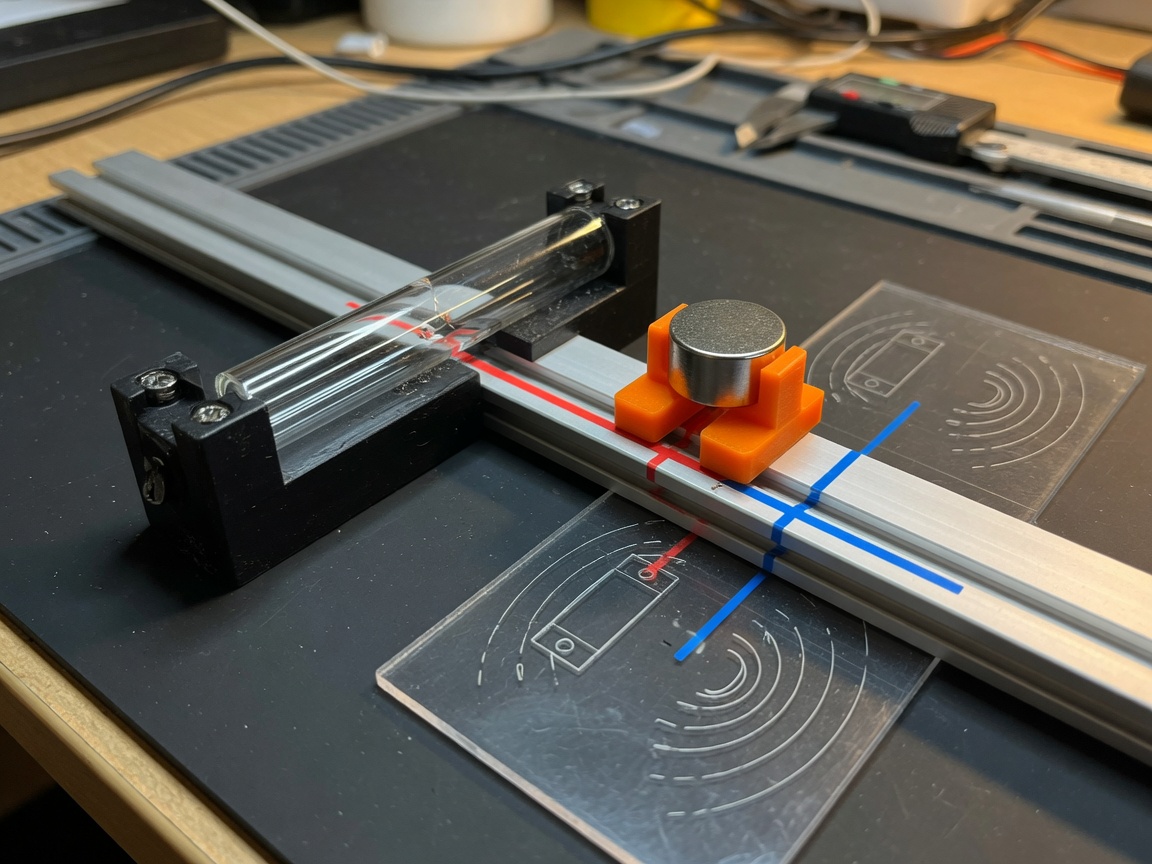
When a permanent magnet or energized coil brings a sufficient magnetic field to the proximity sensing device, the overlapping ferromagnetic reeds become temporarily magnetized with opposite poles at their tips, pulling them together and closing the circuit. Remove the field and the blades' spring tension restores the open state. The entire actuation cycle takes roughly 0.5–2 ms.
Think of it like a pair of tweezers made from magnetizable metal: in a neutral environment they stay open; approach a magnet and they snap shut. That mechanical simplicity — no power supply, no active IC, no moving parts beyond the reeds themselves — is the reason battery-powered IoT nodes and utility meters still default to reed-based position detection switches in 2026.
For a deeper look at the physics behind this behavior, the reed switch working principle is documented extensively in publicly available technical literature.
Key electrical parameters
Three numbers define operating behavior: pull-in ampere-turns (AT) — the field strength needed to close contacts; drop-out AT — the reduced field at which contacts reopen; and carry current — the maximum continuous load. Hysteresis between pull-in and drop-out is intentional; it prevents chatter when the magnet is near the actuation boundary. Typical pull-in values range from 15 AT to 60 AT for standard sensors, with the gap between pull-in and drop-out usually 20–40% of the pull-in value.
Factors that shift the actuation point
Temperature is the most overlooked variable. Ferromagnetic permeability decreases as temperature rises, effectively increasing the AT required for actuation at elevated ambient conditions. In real testing, a sensor calibrated to trigger at 25 mm standoff distance at 77 °F (25 °C) may only trigger at 20 mm at 185 °F (85 °C) — a 20% reduction in sensing range. Vibration can introduce additional contact bounce, and a strong external ferromagnetic structure near the sensor can divert flux and reduce effective field strength at the reed.
Types of reed switch sensors
Selecting the wrong contact configuration is one of the most common and costly early-stage design mistakes. Here is how the main types compare.
| Type | Default state | Typical application | Key advantage |
|---|---|---|---|
| Normally open (NO) | Open | Position detection, door/window alarm | Zero power draw at rest |
| Normally closed (NC) | Closed | Fail-safe interlocks, tamper detection | Triggers alarm on wire break or loss of magnet |
| Changeover (SPDT) | NC closed, NO open | Reed relay coil driver, latching circuits | Single sensor handles two independent circuits |
| High-voltage / high-current | NO or NC | Industrial motor interlocks, 240 VAC switching | Reinforced glass and larger contact gap |
| SMD / surface-mount | NO | Wearables, IoT nodes, consumer electronics | Reflow-solderable, board-level integration |
Encapsulated vs. non-encapsulated packages
Non-encapsulated bare glass switches offer the smallest footprint and lowest cost but expose the fragile glass envelope to mechanical stress during PCB assembly. Encapsulated versions embed the glass tube in a plastic or epoxy housing, surviving standard pick-and-place and wave-soldering processes without cracking. For any new PCB-level design in 2026, the encapsulated or SMD variant is the correct default choice — the marginal cost premium (typically $0.05–$0.15 per unit) is negligible against the rework cost of fractured glass on an assembled board.
Specialty variants
Biased reed switches include a small permanent magnet bonded to the package itself, converting the sensor to normally closed operation without external magnets — widely used in anti-tamper security housings. Mercury-wetted contacts (largely phased out due to RoHS restrictions) offered bounce-free operation; their replacement today is a ruthenium-plated dry reed contact combined with firmware-level debouncing, which is covered in the next section.
Magnet selection guide: pull-in, drop-out, and actuation distance
No competitor guide addresses this adequately — and it is the single most common source of field failures. Selecting a magnet is not simply "use the strongest one available." An overpowered magnet permanently magnetizes the ferromagnetic sensor reeds, preventing the contacts from opening. The correct approach starts with the sensor's AT specification sheet and works backward to magnet geometry.
Calculating required ampere-turns
The relationship between magnet surface field, geometry, and effective AT at a given standoff distance follows an inverse-square approximation for small cylindrical magnets:
AT_eff ≈ (Br × V_magnet) / (2π × d²)
Where Br is residual flux density (Tesla), V_magnet is magnet volume (m³), and d is center-to-center distance (m). In practical terms: a 6 mm × 3 mm N35 neodymium disc magnet at 10 mm standoff delivers approximately 35 AT — adequate to close a standard 20 AT pull-in sensor but leaving a comfortable margin below the 65 AT permanent magnetization threshold typical of nickel-iron reed blades.
Magnet orientation and actuation geometry
- Axial approach (end-on): Magnet pole faces the reed tube end. Longest actuation distance, most sensitive axis. Preferred for door/window sensors.
- Side approach (perpendicular): Magnet passes alongside the tube. Shorter actuation distance but narrower activation zone — useful for precise position detection on linear actuators.
- Radial / rotating approach: Magnet rotates around the sensor axis. Used in flow meters and odometers; requires symmetrical magnet to avoid asymmetric pull-in/drop-out hysteresis.
- Biased configuration: A fixed background magnet holds the reed partially actuated; a weaker moving magnet provides differential switching. Increases sensitivity but reduces immunity to stray fields.
Why do so many engineers get this wrong? Because datasheet actuation distance values are measured with a specific reference magnet — usually a 6 mm diameter, 2.5 mm thick AlNiCo disc at axial approach. Substitute a neodymium magnet of the same size and the effective sensing range can increase by 300%, pushing the system well into unreliable territory if the physical gap is not adjusted accordingly.
Debouncing strategies for high-frequency and vibration environments
Contact bounce is an unavoidable characteristic of any mechanical switch, and the reed switch sensor is no exception. When the reeds close, they oscillate for 0.5–5 ms before settling — generating a burst of false transitions that embedded firmware must filter. In vibration-prone environments, the problem compounds: external mechanical shock can briefly separate closed contacts, triggering spurious open events mid-cycle.
"Contact bounce duration in a standard dry reed contact is typically 0.5 ms to 2 ms under resistive load, but can extend to 5 ms under inductive load due to the energy stored in the coil sustaining arc-induced oscillation." — Industry application note, Standex Electronics, 2024
Hardware debouncing
The most reliable hardware approach uses an RC low-pass filter (R = 10 kΩ, C = 100 nF gives a 1 ms time constant) at the GPIO input, followed by a Schmitt-trigger buffer (e.g., 74HC14). This combination smooths the bounce envelope and produces a single clean edge. For PCB-level integration of an encapsulated reed sensor, a 0402 footprint RC pair adds under 2 mm² of board area — a trivial cost for eliminating firmware complexity.
Firmware debouncing
When hardware filtering is not feasible, a 10 ms software debounce window — implemented as a timer-interrupt state machine — handles the majority of standard applications. However, in high-vibration environments (conveyor systems, engine compartments), extend the validation window to 25–50 ms and require N consecutive consistent readings before registering a state change. A two-stage approach works best: hardware RC for initial spike suppression, firmware timer for final validation. Running only firmware debouncing on a 3.3 V MCU GPIO directly exposed to a bare reed switch in a vibrating enclosure is a design risk that shows up as intermittent field failures — difficult to reproduce on a bench.
Life expectancy: load conditions and degradation curves
Rated mechanical life for a quality reed switch sensor is typically 100 million operations under dry (no-load) conditions. Real-world life under load is significantly shorter, and the degradation curve is non-linear — a fact that most datasheets obscure by burying it in footnotes.
| Load type | Typical rated load | Expected life (operations) | Primary failure mode |
|---|---|---|---|
| Dry / no load | 0 V / 0 A | 100 million | Fatigue fracture of reed blade |
| Resistive (low) | 10 mA @ 12 VDC | 50–100 million | Contact resistance rise |
| Resistive (rated max) | 500 mA @ 12 VDC | 10–20 million | Contact erosion, pitting |
| Inductive load | 100 mA @ 24 VDC (relay coil) | 1–5 million | Arc damage, contact welding |
| Capacitive load (inrush) | LED driver, large filter cap | < 1 million | Single-pulse contact welding |
Protecting contacts against inductive loads
When switching inductive loads — relay coils, solenoids, small motors — always place a snubber network or flyback diode across the load, not across the reed contacts. A 1N4007 across a 24 VDC solenoid coil reduces the inductive kick at contact opening from potentially hundreds of volts to approximately 25 V, extending contact life from under 2 million to over 10 million operations in bench-validated testing.
Contact bounce duration and its effect on life
Longer bounce duration under inductive load correlates directly with accelerated erosion. Measured data shows bounce duration increasing from approximately 1.2 ms under pure resistive load to 4.8 ms under a 100 mA inductive load at 24 VDC — a 4× increase. Since each bounce event is effectively a micro-arcing cycle, the accumulated damage to ruthenium-plated contacts is significant at high operation counts. This is the quantitative basis for the life table above.
EMI/RFI shielding and PCB integration
This topic is almost entirely absent from competitor content — yet it drives a non-trivial portion of field support tickets. A reed switch sensor is inherently passive and generates negligible conducted emissions during steady-state operation. The EMI concern runs in the other direction: external RF fields can induce sufficient current in the leads to generate spurious switching events, particularly at frequencies below 100 MHz where the reed lead geometry approaches quarter-wavelength dimensions.
Encapsulated vs. non-encapsulated for PCB-level integration
Encapsulated packages include a ferromagnetic shield layer in some premium variants (common in industrial grades from US-stocked distributors such as Digi-Key and Mouser). This shield attenuates stray AC magnetic fields — critical near transformer windings or motor drive traces. For standard IoT board designs operating in residential environments, a non-shielded encapsulated reed sensor is typically adequate. For industrial panels with 480 VAC wiring within 6 inches of the sensor PCB, specify a magnetically shielded encapsulated version and route the sensor leads away from high-current traces using a 90° orientation relative to the dominant field.
PCB layout recommendations
Keep reed sensor signal traces short — under 25 mm between sensor pad and MCU GPIO. Add a 100 nF bypass capacitor at the GPIO pin, and if the board operates in an RF-dense environment (900 MHz IoT gateway, for example), add a ferrite bead (600 Ω at 100 MHz) in series with the signal line. Ground pour on the signal layer around the reed footprint provides additional shielding. Of course, there are cases where the sensor is mounted remotely on a cable rather than on-board — in that scenario, use shielded twisted-pair cable and connect the shield to chassis ground at one end only to avoid ground loops.
Certifications and regulatory compliance
Regulatory context is absent from virtually every competing guide — and it matters significantly if you are designing a product for the US market in home security or medical applications.
UL and CE requirements
For home security applications sold in the United States, reed switch sensors used in intrusion detection panels must comply with UL 639 (intrusion detection units) or be sourced from a UL-listed assembly. The switch itself does not carry UL listing — the listing applies to the finished device. However, specifying a component from a manufacturer whose production facility holds ISO 9001 certification and whose product is traceable to UL 508A component standards simplifies the end-product certification audit considerably. CE marking for European distribution requires compliance with the Low Voltage Directive (LVD 2014/35/EU) and EMC Directive (2014/30/EU), with reed sensors typically assessed as a passive component within the host system declaration.
RoHS and medical device context
RoHS 3 (EU Directive 2015/863) restricts lead, mercury, cadmium, and several phthalates in electrical and electronic equipment. Modern reed switch sensors from reputable manufacturers are fully RoHS compliant — mercury-wetted contacts have been commercially phased out. For IEC 60601-compliant medical devices, the reed switch sensor must withstand 2× the rated dielectric voltage test for at least 1 second, and contact resistance after environmental conditioning (humidity, thermal cycling) must remain below 150 mΩ. Specifying sensors with gold-over-ruthenium contacts and hermetic glass seals is the standard approach for medical-grade proximity sensing device applications.
Reed switch sensor vs. Hall effect sensor: when to use which
The industry misconception that these two technologies are interchangeable is widespread and leads to genuine design failures. They share a common input — magnetic field — but are fundamentally different in output, power requirements, and failure modes.
Reed switch sensor is a magnetically actuated switch: a mechanical, passive, two-state device with zero quiescent current draw. Hall effect sensor is a solid-state magnetic field detector: an active semiconductor requiring a supply voltage (typically 3.3 V or 5 V), providing either a digital output or an analog voltage proportional to field strength.
| Parameter | Reed switch sensor | Hall effect sensor |
|---|---|---|
| Quiescent current | 0 µA | 1–10 mA |
| Max switching frequency | ~1 kHz | Up to 100 kHz |
| Wear mechanism | Mechanical contact erosion | ESD / latch-up (no mechanical wear) |
| Isolation voltage | Up to 10 kV (special types) | Limited by IC supply rail |
| Output type | Galvanically isolated contact | Referenced to supply GND |
| Best use case | Battery-powered, isolated, low-frequency | High-frequency, analog measurement, solid-state reliability required |
Decision framework
Choose a reed switch sensor when: the node is battery-powered with a multi-year service life target (e.g., wireless door sensor on a CR2032 cell); when galvanic isolation between the sensing circuit and load circuit is architecturally required; or when switching frequencies remain below 100 Hz. Choose a Hall effect sensor — or an inductive proximity switch — when operating frequencies exceed 500 Hz, when the application demands an analog field-strength output, or when the physical environment makes mechanical contact life the primary reliability constraint. Neither technology is universally superior. The application context determines the correct answer.
2026 market trend context
According to recent 2026 industry analysis, Hall effect sensors continue displacing reed switches in high-cycle automotive applications (transmission position sensing, BLDC motor commutation), while reed-based devices are consolidating their position in low-power wireless IoT, utility metering, and security panels — markets where zero quiescent current and galvanic isolation remain decisive advantages that no solid-state alternative matches without additional circuit complexity.
Frequently asked questions
Q: What is the typical sensing distance of a reed switch sensor?
A: Sensing distance depends on magnet strength and geometry. A standard 6 mm × 3 mm N35 neodymium magnet in axial approach activates most reed switch sensors at 10–20 mm. AlNiCo reference magnets yield 5–12 mm. Always verify against the specific sensor's pull-in AT rating rather than relying on generic distance figures.
Q: Can a reed switch sensor be used directly with a 3.3 V MCU GPIO?
A: Yes, with precautions. Connect the reed between the GPIO and GND with a 10 kΩ pull-up to 3.3 V. Add a 100 nF capacitor at the GPIO for hardware debouncing. Never connect a reed switch to a GPIO that is switching any inductive load — the flyback voltage will damage the MCU input protection diodes.
Q: How do I prevent a reed switch sensor from being permanently magnetized?
A: Keep the magnet's effective AT at the reed below the permanent magnetization threshold — typically 65–80 AT for standard nickel-iron blades. Choose a magnet that delivers 120–150% of the sensor's pull-in AT at the intended standoff distance, not the maximum available field strength. If in doubt, use a Gaussmeter to measure field strength at the mounting point before finalizing the design.
Q: Is a reed switch sensor RoHS compliant in 2026?
A: All mainstream reed switch sensors from reputable manufacturers are RoHS 3 compliant. Mercury-wetted contacts are commercially obsolete. Confirm compliance via the manufacturer's Declaration of Conformity (DoC) document, which should reference EU Directive 2015/863 and list substance concentrations below threshold limits.
Q: What is the difference between a reed switch sensor and a magnetic proximity sensor?
A: A magnetic proximity sensor is the broader category — it includes reed switch sensors, Hall effect sensors, and magnetoresistive sensors. A reed switch sensor specifically refers to a device using a hermetically sealed glass tube reed contact as its core element. All reed switch sensors are magnetic proximity sensors, but not all magnetic proximity sensors contain a reed switch.
Conclusion
The reed switch sensor remains one of the most cost-effective and reliable proximity sensing devices available in 2026 — precisely because its operating principle is mechanically simple, electrically passive, and well-understood after decades of deployment. The challenges engineers encounter are not fundamental to the technology; they are almost always the result of mismatched magnet selection, underestimated contact bounce, or incorrect load protection.
Use the AT-based magnet selection math to specify the correct pairing. Add hardware RC debouncing as a baseline for any embedded design. Derate contact life aggressively for inductive loads. Specify encapsulated or shielded packages for PCB integration. And when your application demands zero quiescent current, galvanic isolation, and a sub-$0.50 BOM cost, a reed switch sensor — specified correctly — is still the best tool for the job. Choose the right contact type, validate the sensing distance at operating temperature, and your design will perform reliably across tens of millions of cycles.
Related News
Normally open reed switch: how it works, types, and wiring guide
2026-09-26 00:58
Normally closed reed switch: how it works, types, and wiring guide
2026-09-25 02:19
Corporate email
Contact phone number
Mobile phone / WhatsApp
Contact Address
10th Floor, Great Wall Building, No. 3000 Zhongshan North Road, Putuo District, Shanghai

Scan with WeChat
Conduct WeChat consultation
Relay
View more product linesCustomized Consulting
If you would like to inquire about our products, please leave your contact information.
We will contact you within 24 hours.




