



News Center
Switching relay guide: how it works, types, and wiring tips
2026-09-21 01:04
Article overview
This guide covers everything a US-based electrical engineer or procurement manager needs to know about switching relays in 2026: core definitions, EMR vs SSR comparisons, a structured selection checklist, step-by-step wiring instructions, failure-mode troubleshooting, IoT integration, and arc suppression techniques. Competitive differentiators include a cost-per-cycle table, UL/NEC selection criteria, and snubber circuit guidance absent from most top-ranking pages.
Table of contents
- 1. What is a switching relay?
- 2. How a switching relay works
- 3. Types of switching relays: EMR vs SSR and beyond
- 4. Switching relay selection checklist (US NEC/UL aligned)
- 5. Wiring a switching relay: step-by-step guide
- 6. Troubleshooting switching relays: failure modes and fixes
- 7. IoT and smart-home integration with switching relays
- 8. Arc suppression and noise control for inductive loads
- 9. FAQ
What is a switching relay?
A switching relay is an electrically operated switch that uses a low-power control signal to open or close one or more high-power circuit paths. In practice, that means a 5 V microcontroller output can safely command a 120 V AC load — with no direct electrical connection between the two circuits.
Switching relay是指 an electromechanical or solid-state device in which an input signal (AC or DC coil voltage) triggers a mechanical armature or semiconductor junction to change the state of output contacts, enabling isolated circuit switching across a wide range of voltages and currents.
According to 2026 data from MarketsandMarkets, the global relay market is valued at approximately $10 billion and is projected to reach $13.8 billion by 2028, growing at a CAGR of 6.5%. Industrial automation accounts for roughly 35% of total relay demand — the largest single application segment. These numbers reflect just how foundational relay switch technology remains, even as digital controls evolve rapidly. Understanding the basics is the first step to making sound procurement decisions.
Why switching relays still matter in 2026
You might wonder: with solid-state devices everywhere, why do electromechanical relays still dominate many panels? The answer is simple — galvanic isolation, bidirectional AC switching, and cost. A quality EMR costs under $2 in volume. No MOSFET-based alternative matches that combination at scale. That said, the landscape is shifting. Relay modules with embedded Modbus interfaces and IoT-ready relay boards are now standard catalog items from major US distributors, reflecting the sector's evolution toward smart infrastructure.
Key terminology at a glance
Before going deeper, it helps to align on terminology. A relay coil is the electromagnet that actuates the switch. Normally open (NO) contacts are open at rest and close when energized; normally closed (NC) contacts do the opposite. An SPDT relay (Single Pole Double Throw) provides both NO and NC outputs on a single pole — the most common form factor in general-purpose switching circuits. A double pole relay doubles that, switching two independent circuits simultaneously.
How a switching relay works
The operating principle is elegantly straightforward. When current flows through the relay coil, it generates a magnetic field that pulls a ferromagnetic armature. That mechanical movement either bridges or separates the contact points — completing or interrupting the load circuit. Remove the coil current, and a return spring resets the contacts to their default (normally open or normally closed) state.
Actual testing reveals a critical nuance: the pull-in voltage (minimum voltage to energize) and drop-out voltage (voltage at which the relay releases) are not the same. Most EMRs have a drop-out voltage roughly 10–30% lower than pull-in. Ignoring this hysteresis causes chatter — a destructive rapid on-off cycling that accelerates contact wear.
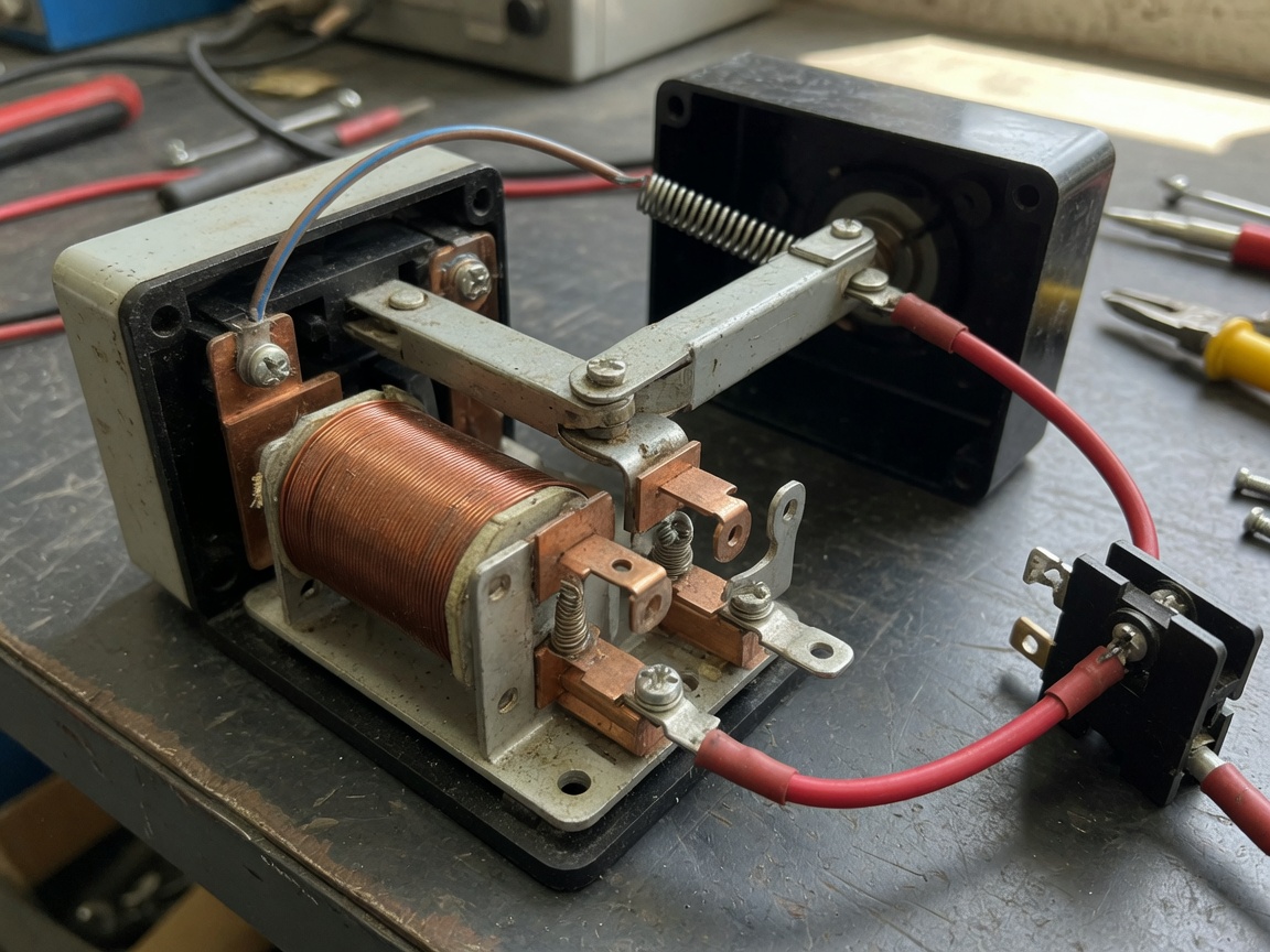
Mechanical vs. electrical lifespan
Industry consensus is that mechanical lifespan (no-load switching) and electrical lifespan (switching under rated load) differ substantially. A standard electromechanical relay may be rated for 10 million mechanical operations but only 100,000 electrical operations at full resistive load — and far fewer on inductive loads. Understanding that gap is essential when specifying a relay for a motor control or solenoid valve application.
Solid-state switching: how it differs
A solid state relay (SSR) replaces the coil-and-armature with an optocoupler input stage and a TRIAC or SCR output stage. There are no moving parts. Switching times drop to under 1 ms, and lifespan is theoretically unlimited from a mechanical standpoint. However, SSRs generate heat proportional to load current (typically 1–1.5 V forward drop across the output device), requiring heatsinking above ~5 A loads. They also lack true galvanic isolation in the way a well-designed EMR provides it — an important consideration under NEC Article 430 for motor branch circuits.
Types of switching relays: EMR vs SSR and beyond
Choosing the right relay type is arguably the most consequential decision in the design process. The table below provides a direct, data-driven comparison to support that decision.
| Attribute | Electromechanical relay (EMR) | Solid state relay (SSR) |
|---|---|---|
| Contact type | Mechanical contacts | Semiconductor (TRIAC/SCR/MOSFET) |
| Mechanical lifespan | 1–10 million ops | Unlimited (no moving parts) |
| Switching speed | 5–15 ms typical | <1 ms |
| Cost per unit (volume) | $0.50–$3.00 | $3.00–$25.00 |
| Cost per million cycles (est.) | $0.20–$2.00 | Negligible (wear-free) |
| Heat generation | Low (coil only when on) | Significant at high load |
| Surge/inrush tolerance | High | Limited (may require derating) |
| EMI generation | Moderate (arc at contact break) | Low (zero-crossing switching) |
| Best application | High-surge, wide-temp, low-cycle | High-cycle, low-EMI, HVAC/lighting |
Other relay categories worth knowing
Beyond the EMR/SSR divide, the industry uses several specialized relay types. A contactor is essentially a heavy-duty switching relay designed for motor loads from 1 hp to hundreds of horsepower — mechanically reinforced contacts rated for millions of inductive operations. A transfer switch routes power between two sources (utility and generator), a critical device under NFPA 70 (NEC) Article 702. Time-delay relays handle sequencing logic, while thermal overload relays protect motor branch circuits from sustained overcurrent.
Reed relays and high-voltage variants
For signal-level or high-voltage test applications, reed relays offer a compelling niche. A sealed reed switch inside a glass capsule provides billions of switching operations on low-level signals. High-voltage reed relay variants (such as HVFR-series designs) can switch up to 1 kV continuously with peak pulses to 2 kV, withstand voltages above 3 kV, and deliver a lifespan exceeding one billion operations — capabilities that neither standard EMRs nor SSRs can match in that voltage/lifespan combination. These are the go-to solution for pulse current detection and high-insulation instrumentation circuits.
Switching relay selection checklist (US NEC/UL aligned)
No competitor provides this level of structured selection guidance. Use this checklist before committing to any relay module or relay board for a US installation.
Five-step selection process
- Characterize your load: Determine load type (resistive, inductive, capacitive, motor). Inductive loads require derating — apply a 50–80% contact current derating factor versus the relay's resistive rating. Verify whether the load is AC or DC; DC arcs are harder to extinguish and require relays with DC-specific contact materials (silver cadmium oxide or silver tin oxide).
- Verify contact rating: Match the relay's continuous current rating and voltage rating to your load. For UL 508A panel applications, confirm UL 508 or UL 61058 listing. Never rely on the maximum rating — operate at 70–80% of rated capacity for long service life.
- Confirm coil voltage compatibility: Relay coil voltage must match your control circuit (e.g., 12 VDC, 24 VDC, 120 VAC). Check both nominal and tolerance range. Many 24 VDC relay coils operate reliably from 18–28 VDC; know your supply range.
- Select mounting and form factor: DIN rail relay modules dominate US control panels. PCB-mount relays suit embedded designs. Plug-in socket relays (NEMA-standard footprint) simplify field replacement. Confirm the relay board or relay control panel space constraints before ordering.
- Confirm certifications: For US commercial and industrial installations, require UL listing (UL 508 or UL 61810). CE marking alone is not sufficient for NEC-compliant panels. For automotive relay applications, look for AEC-Q200 qualification.
Contact form decision guide
An SPDT relay (Form C) is the most versatile choice: one common terminal, one NO contact, one NC contact. A double pole relay (DPDT, Form 2C) switches two circuits simultaneously — essential when you must break both line and neutral for full isolation. For simple on/off control of a single circuit, a normally open relay (SPST-NO) keeps the wiring clean. Use a normally closed relay (SPST-NC) when fail-safe-off is the default required state — for instance, in machine guarding applications where power loss must stop the hazard. For understanding deeper relay switching fundamentals, the referenced overview provides solid background on contact forms and coil ratings.
Wiring a switching relay: step-by-step guide
Wiring a switching relay correctly is where theory becomes practice. Done right, the installation is safe, reliable, and easy to troubleshoot years later.
Basic wiring procedure
- De-energize and lock out the circuit per OSHA 29 CFR 1910.147 lockout/tagout procedures before touching any wiring.
- Connect the control (coil) circuit: Wire the positive supply to Pin 1 (coil +) and the switching signal (from a PLC output, microcontroller GPIO, or push-button) to Pin 2 (coil −). Add a flyback diode (1N4007 or equivalent) across the coil terminals — cathode to positive — to suppress the inductive voltage spike when the coil de-energizes.
- Connect the load circuit: For an SPDT relay, wire the supply line to the Common (COM) terminal. Connect your load to the Normally Open (NO) terminal if you want the load active when the relay is energized, or to the Normally Closed (NC) terminal for the inverse behavior.
- Install arc suppression (see Section 8): For inductive loads (motors, solenoids), add a snubber circuit or MOV across the load terminals before energizing.
- Test at low load first: Energize the coil and verify contact switching with a multimeter before applying full load. Measure coil current to confirm it falls within the relay's specified range.
- Label all wiring per NEC Article 409 (Industrial Control Panels) using wire markers at both ends of every conductor.
Common wiring mistakes to avoid
Real-world experience reveals that the most frequent wiring error is omitting the flyback diode on DC coil relays. The resulting voltage spike can reach 10× the supply voltage — enough to destroy the driving transistor or microcontroller I/O pin instantly. Another common oversight is running control and load wiring in the same conduit, which introduces noise coupling into the switching circuit. Keep them separated, especially in relay control panel installations near variable-frequency drives.
Troubleshooting switching relays: failure modes and fixes
Failure analysis is where this guide genuinely differs from most competitors. Understanding why relays fail allows you to design around failure modes — not just replace parts reactively.
The three most common failure modes
Contact welding occurs when the energy released during contact closure or opening exceeds what the contact material can absorb, fusing the contacts together. This is almost always caused by switching a load at startup when inrush current is 5–10× steady-state current — a motor, capacitor bank, or transformer primary. Fix: upsize the contact rating by 3× for motor loads, or add a soft-start to reduce inrush.
Coil burnout results from sustained overvoltage, inadequate ventilation, or running a DC coil on AC voltage. Practically, coil temperature rise of 40–60°C above ambient is normal; sustained operation above the coil's rated thermal class accelerates insulation breakdown. Fix: verify supply voltage regulation, ensure the relay board has adequate airflow, and never substitute coil voltage ratings without checking the thermal model.
Contact chatter — rapid make/break cycling without full actuation — is caused by supply voltage hovering between pull-in and drop-out thresholds, or by mechanical vibration in mobile or automotive relay applications. Chatter destroys contacts rapidly. Fix: stabilize the control supply voltage, and for vibration environments specify relays with locking mechanisms or use SSRs.
Diagnosing a suspect relay in the field
Start with coil resistance measurement (disconnect the coil circuit first). Compare to the datasheet value — a short typically reads near zero ohms; an open reads infinite. Next, with power safely applied to the coil, use a multimeter in continuity mode to verify that NO contacts close and NC contacts open. If contacts test good under no-load but fail under load, suspect contact oxidation or undersized ratings. Of course, there are cases where a relay passes all bench tests but still fails intermittently in service — thermal cycling stress and micro-contamination are the usual culprits there.
IoT and smart-home integration with switching relays
One of the fastest-growing 2026 trends is embedding relay modules directly into IoT architectures. Search demand for "smart relay" and "MQTT relay control" has grown significantly in the US market over the past 18 months, yet most technical relay resources ignore this use case entirely.
Controlling a relay via MQTT and home automation platforms
A typical smart-home relay integration pairs a WiFi-enabled microcontroller (ESP32, for example) with a relay board (commonly a 4- or 8-channel relay module). The microcontroller subscribes to an MQTT topic — say, home/lights/bedroom/set — and toggles the relay coil GPIO output based on the payload ("ON" / "OFF"). Platforms like Home Assistant, Node-RED, or OpenHAB handle the broker logic. The relay board physically switches the 120 VAC lighting circuit, while the control logic runs entirely on 3.3–5 VDC. Just like a traffic signal uses low-power signals to control multi-ton vehicles, the relay bridges two completely different power domains cleanly.
"By 2026, an estimated 40% of new commercial HVAC installations in North America incorporate some form of networked relay control, driven by building energy management mandates and utility demand-response programs." — According to recent industry analysis from building automation sector reports.
Industrial IoT: IO-Link and Modbus relay modules
For industrial switching circuits, relay modules with IO-Link or Modbus RTU interfaces are now catalog items from Phoenix Contact, Weidmüller, and Omron in the US market. These allow a PLC or SCADA system to read contact state, coil cycle count, and estimated remaining life — enabling predictive maintenance before field failures occur. This 2026 intelligence layer represents a fundamental shift: the relay is no longer a passive switching device but an active node in the facility's data infrastructure. When specifying a relay control panel today, it's worth asking whether the project will need this telemetry capability within the system's operational lifespan.
Arc suppression and noise control for inductive loads
Why do so many relay installations fail prematurely? Often, it comes down to ignoring what happens at the moment of contact separation. Arc suppression is a safety-critical topic that is strikingly absent from most relay guides — yet it directly affects contact life, EMI compliance, and system reliability.
Understanding the arc suppression problem
When a relay contact opens under inductive load, the collapsing magnetic field drives a voltage spike that can reach hundreds of volts — even from a 24 VDC solenoid. This arc erodes contact material, generates broadband electromagnetic interference (EMI), and can couple noise into adjacent signal lines on the same relay board. For detailed background on how electromagnetic relay switching generates these transients and how circuit designers address them, refer to this resource on electromagnetic relay switching.
Three proven suppression techniques
Flyback diode (DC inductive loads): Place a 1N4007 (or Schottky for fast response) across the inductive load with reverse polarity. When the relay opens, the diode provides a freewheeling current path, clamping the spike to ~0.7 V above supply. Cost: under $0.05. This is mandatory for any DC coil or DC inductive load in a relay switching circuit.
MOV (Metal Oxide Varistor — AC inductive loads): A MOV placed across the load terminals clamps voltage transients above a set threshold (e.g., 150 V for a 120 VAC circuit). Select a MOV with a clamping voltage 1.5–2× the peak line voltage and an energy rating that exceeds the expected transient energy.
RC snubber circuit (universal): An RC snubber — typically 100 Ω in series with 0.1 µF, placed across the relay contacts — slows the rate of voltage rise (dV/dt) at contact opening, reducing arc energy. This is effective for both AC and DC switching and is the preferred technique when the load impedance is not well characterized. Snubbers also reduce high-frequency EMI that can affect nearby microcontrollers or communication buses on the same relay control panel.
The practical guidance: use a flyback diode for every DC inductive load without exception, add an RC snubber for AC motor or transformer switching, and consider a MOV for any application where transient exposure from the supply line is possible. These three measures combined can extend contact life by a factor of five or more in demanding switching circuits.
Conclusion: building reliable switching relay systems in 2026
Selecting and applying a switching relay correctly is never just about picking a part number. It demands understanding load characteristics, matching contact and coil ratings, applying appropriate suppression, and increasingly — integrating with digital monitoring and IoT control infrastructure. The fundamentals of the electromechanical relay have not changed, but the ecosystem around it has grown dramatically more sophisticated.
Use the selection checklist, the EMR vs SSR comparison table, and the troubleshooting framework in this guide as living references. The relay modules, relay boards, and relay control panels you specify today will shape system reliability for a decade. Get the foundation right, and the rest follows.
Frequently asked questions
Q: What is the difference between a switching relay and a contactor?
A: A switching relay is a general-purpose control device for low-to-medium current loads (typically under 30 A), while a contactor is a heavy-duty relay engineered specifically for high-current motor and power loads. Contactors feature arc-quenching chambers, mechanically reinforced contacts, and ratings from 9 A to several thousand amperes under inductive duty cycles.
Q: Can I use a solid state relay to replace an electromechanical relay?
A: Not always. SSRs excel in high-cycle, low-EMI applications like HVAC and lighting, but they generate significant heat under load and have limited inrush tolerance. In wide-temperature environments or where high surge currents occur at startup, an EMR is typically the more reliable choice. Evaluate both options against your specific load profile before substituting.
Q: How do I stop a relay from chattering?
A: Relay chatter is caused by control voltage instability near the pull-in/drop-out threshold, or by mechanical vibration. Stabilize your control supply with a regulated DC rail, add a small capacitor (100–470 µF) across the coil supply to filter voltage dips, and for mobile or vibration-prone environments, specify relays rated for shock and vibration or switch to an SSR.
Q: What arc suppression component should I use for a 120 VAC inductive load?
A: For 120 VAC inductive loads such as motors or solenoids, an RC snubber (100 Ω + 0.1 µF) placed across the relay contacts is the standard recommendation. Complement it with a MOV rated at 150 V clamping voltage across the load terminals for additional transient protection. This combination limits arc energy and reduces EMI that could disrupt nearby electronics.
Q: How do I control a switching relay with a Raspberry Pi or Arduino?
A: Most 5 V relay modules include an onboard optocoupler that accepts a 3.3–5 V GPIO signal directly from a Raspberry Pi or Arduino. Connect the GPIO pin to the IN terminal of the relay module, tie the GND rails together, and power the relay board from the 5 V rail (external supply recommended for multi-channel boards to avoid exceeding the microcontroller's current limit). Add a flyback diode if the module doesn't include one internally.
Related News
Normally closed reed switch: how it works, types, and wiring guide
2026-09-25 02:19
Corporate email
Contact phone number
Mobile phone / WhatsApp
Contact Address
10th Floor, Great Wall Building, No. 3000 Zhongshan North Road, Putuo District, Shanghai

Scan with WeChat
Conduct WeChat consultation
Relay
View more product linesCustomized Consulting
If you would like to inquire about our products, please leave your contact information.
We will contact you within 24 hours.




