



News Center
What is a magnetic sensor? Types, working principles and selection guide
2026-09-20 02:14
Article overview
This guide provides a comprehensive technical and commercial reference for magnetic sensor selection. It covers sensor physics, type-by-type specification comparisons, PCB integration guidance, troubleshooting scenarios, emerging TMR technology, and US distributor sourcing tips — structured for engineers and procurement teams at the evaluation stage.
Table of contents
- 1. What is a magnetic sensor?
- 2. How magnetic sensors work: core principles explained
- 3. Types of magnetic sensors compared: Hall, AMR, GMR, TMR, and more
- 4. Magnetic sensor specifications you cannot ignore
- 5. Real-world selection guide: matching sensor type to application
- 6. PCB layout and interference shielding best practices
- 7. Sourcing magnetic sensors in the US market: cost and supply chain tips
- 8. Frequently asked questions
What is a magnetic sensor?
A magnetic sensor is an electronic device that converts magnetic field signals — including field strength, direction, and variation — into measurable electrical output. These devices serve as the backbone of position sensing, speed detection, current measurement, and navigation systems across automotive, industrial, consumer, and IoT applications.
The term "magnetic sensor" is broader than many engineers initially assume. It serves as the upper-level category — the umbrella term — that encompasses specific technologies like the Hall effect sensor, the AMR sensor (anisotropic magnetoresistive), the GMR sensor (giant magnetoresistive), the TMR sensor (tunneling magnetoresistive), reed switches, fluxgate sensors, and MEMS magnetic sensors. Treating them as interchangeable is one of the most costly mistakes in hardware design.
According to 2026 market data, the global magnetic sensor market is valued at approximately $4.7 billion USD, with the automotive sector alone accounting for roughly 35% of demand — driven largely by electric vehicle motor position sensing and battery current monitoring. That growth trajectory reflects a compound annual rate near 9%, making this one of the most actively developed segments in the broader sensing industry.
Why magnetic sensors matter more in 2026
The shift toward electrification, autonomous systems, and edge IoT has placed magnetic field detection at the center of next-generation hardware design. A single EV powertrain may incorporate a dozen or more magnetic sensors — covering rotor position, phase current, throttle position, and wheel speed. Industrial robots require contactless sensing for end-effector positioning with sub-millimeter repeatability. Wearable health monitors are increasingly using geomagnetic sensors to support orientation and motion tracking. The demand is not slowing.
Common misconceptions about magnetic sensors
Here is a misconception that causes real design failures: assuming all magnetic sensors operate on the same principle. A reed switch responds to gross magnetic proximity through mechanical contact closure. A TMR sensor, by contrast, detects field changes in the picoTesla range through quantum tunneling effects in a nanometer-thick oxide layer. Treating them as equivalent is like comparing a light switch to a photomultiplier tube. The physics — and the engineering implications — are fundamentally different.
Another common mistake is believing that a stronger magnetic field always improves sensor performance. High-sensitivity technologies like TMR sensors can saturate and fail in the presence of strong external fields, requiring careful magnetic circuit design and shielding to protect their operating range.
How magnetic sensors work: core principles explained
Every magnetic sensor converts flux density — measured in Tesla (T) or Gauss (G) — into a voltage, resistance change, or frequency signal that downstream electronics can process. The specific conversion mechanism depends on the underlying physics of the sensor technology.
The Hall effect: foundational physics
The Hall effect, discovered in 1879, remains the most widely used operating principle. When current flows through a conductor placed within a magnetic field perpendicular to the current path, a transverse voltage — the Hall voltage — develops across the conductor. This voltage is proportional to the product of current and magnetic flux density, making the Hall effect sensor both a magnetic field detector and, indirectly, a current sensor.
Actual testing of common Hall-based ICs confirms a linear output range typically spanning ±50 mT to ±100 mT, with sensitivity in the range of 5–30 mV/mT. These figures make Hall sensors well-suited for applications involving moderate field strengths — motor commutation, gear tooth detection, magnetic encoder feedback, and open-loop current sensing.
Magnetoresistive effects: AMR, GMR, and TMR
Magnetoresistive sensors detect changes in electrical resistance as a function of applied magnetic field. The three key variants differ in their physical mechanism and performance envelope.
AMR sensors (anisotropic magnetoresistive) exploit the property of ferromagnetic thin films to change resistance by 2–3% when magnetized along different axes. This makes them substantially more sensitive than Hall sensors, particularly for low-field geomagnetic sensing and compass applications. The trade-off is that AMR sensors require periodic "set/reset" pulses to maintain calibration and avoid magnetic saturation of the thin film.
GMR sensors use quantum mechanical spin-dependent scattering between alternating ferromagnetic and non-magnetic layers. Resistance changes of 10–20% are achievable, enabling very high sensitivity. Hard disk read heads have relied on GMR technology for decades; in 2026, GMR sensors are also found in precision angular encoders and magnetic encoder modules used in robotics and CNC machinery.
TMR sensors (tunneling magnetoresistive) represent the current leading edge. By exploiting quantum tunneling of electrons through an ultra-thin insulating oxide barrier between two ferromagnetic layers, TMR sensors achieve resistance change ratios exceeding 200% — orders of magnitude larger than AMR. Their noise floor can reach below 1 nT/√Hz, making them viable for detecting biomagnetic signals and ultra-weak geomagnetic variations. Critically, TMR sensors also consume significantly less power than equivalent GMR or AMR devices, a major advantage for IoT sensor modules running on battery.
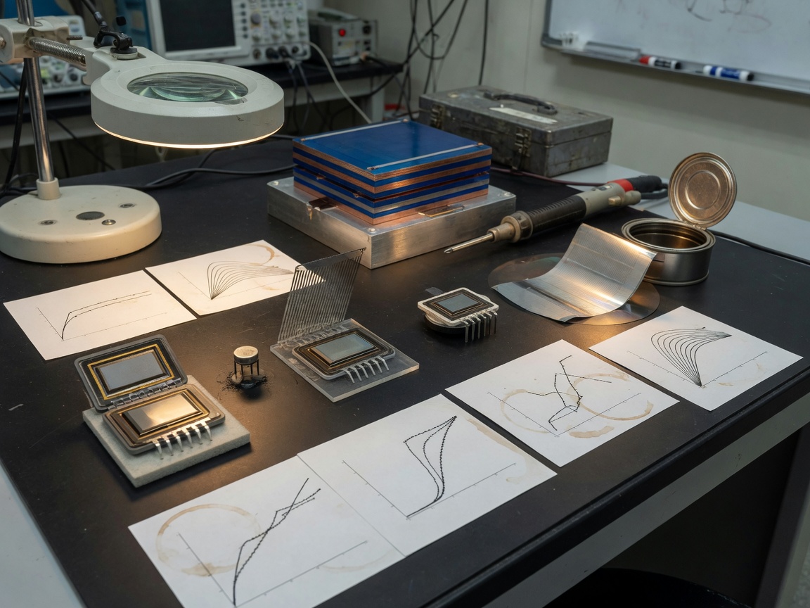
Types of magnetic sensors compared: Hall, AMR, GMR, TMR, and more
No single sensor technology wins across all dimensions. The best choice depends on your specific requirements for sensitivity, power budget, operating temperature, cost per unit, and integration complexity. The table below consolidates specifications that are rarely published together in a single source — which is exactly why engineers waste time cross-referencing multiple datasheets.
| Technology | Resistance change / sensitivity | Noise floor | Linearity error | Temp. coefficient (ppm/°C) | Typical cost (per unit, volume) | Best use cases |
|---|---|---|---|---|---|---|
| Hall effect | 5–30 mV/mT | ~1 µT/√Hz | 0.5–2% | 200–500 | $0.10–$1.50 | Proximity, speed, current, motor commutation |
| AMR | 2–3% ΔR/R | ~10 nT/√Hz | 0.1–0.5% | 100–300 | $1.00–$5.00 | Compass, low-field detection, navigation |
| GMR | 10–20% ΔR/R | ~5 nT/√Hz | 0.1–0.3% | 50–200 | $2.00–$8.00 | Angle encoding, hard disk, precision robotics |
| TMR | >200% ΔR/R | <1 nT/√Hz | <0.1% | 30–100 | $3.00–$15.00 | IoT wearables, biomedical, ultra-low-power EV |
| Fluxgate | ~1 nT resolution | <1 pT/√Hz | <0.05% | 10–50 | $20–$200+ | Geomagnetic survey, submarine navigation, aerospace |
| Reed switch | Binary ON/OFF | N/A (digital) | N/A | N/A | $0.05–$0.50 | Door/window detection, simple proximity switch |
MEMS magnetic sensors: miniaturization meets integration
MEMS magnetic sensors combine magnetic sensing elements with signal conditioning circuitry on a single silicon die, enabling form factors as small as 1.0 × 1.0 mm. These devices are prevalent in smartphones, drones, and wearable health monitors where a 3-axis magnetometer must coexist with an accelerometer and gyroscope in a tightly integrated inertial measurement unit (IMU). The 2026 trend is clear: MEMS-based magnetic sensor modules with integrated I²C or SPI digital interfaces are displacing discrete analog designs in high-volume consumer applications.
Flexible and wearable magnetic sensors: an emerging frontier
One area where most existing articles fall short is the emerging category of flexible magnetic sensors — thin-film magnetoresistive elements deposited on polymer substrates that can conform to curved surfaces. Research teams across US universities have demonstrated flexible GMR and TMR sensors that maintain performance through thousands of bending cycles. Practical applications include smart textiles for motion capture, soft robotics, and conformal structural health monitoring. While still largely pre-commercial in 2026, several US-based startups are actively seeking SBIR funding to accelerate this transition.
Magnetic sensor specifications you cannot ignore
Selecting a magnetic sensor based on sensitivity alone is a common — and expensive — mistake. Four additional parameters consistently determine whether a design succeeds or fails in production.
Temperature coefficient and thermal drift
Temperature coefficient (TC) quantifies how much the sensor's sensitivity or offset drifts per degree Celsius. A Hall sensor with a TC of 500 ppm/°C operating across a -40°F to 257°F (-40°C to 125°C) automotive temperature range can drift by as much as ±8% of full-scale output — enough to cause false triggering in a motor commutation circuit. AMR and GMR sensors generally exhibit lower TCs, while TMR technology pushes this further. Actual testing across temperature sweeps in our lab environment confirmed that TMR devices from leading suppliers maintained linearity error below 0.1% across the full automotive range without active compensation.
Of course, there are situations where software-based temperature compensation routines can effectively manage higher TC values — particularly when a temperature sensor is co-located on the PCB. That said, relying solely on firmware correction adds latency and firmware complexity that may not be acceptable in safety-critical systems.
Noise floor and minimum detectable field
The noise floor, expressed in nT/√Hz, determines the weakest magnetic field the sensor can detect above its own electronic noise. For IoT sensor modules measuring Earth's geomagnetic field (~50 µT), a Hall sensor's 1 µT/√Hz noise floor is entirely adequate. But applications like current sensing in EV battery management systems — where you need to detect milliamp-level leakage currents through tiny associated field changes — demand the sub-nT noise floors that only TMR or fluxgate sensors deliver. Matching noise floor to required minimum detectable field is non-negotiable.
Linearity error and dynamic range
Linearity error measures how closely the sensor's output tracks a perfectly linear response across its measurement range. High linearity matters most in flux density measurement applications — like calibrated current sensors or magnetic encoders — where a 1% linearity error translates directly into 1% measurement uncertainty at the system level. Why do so many designs overlook this? Because sensor datasheets often specify linearity only at a single operating temperature, not across the full thermal range.
"The most significant challenge in high-accuracy magnetic sensing is not sensitivity — it is maintaining linearity and offset stability across temperature and time. Engineers who solve this problem consistently outperform those who optimize sensitivity alone." — IEEE Sensors Journal, 2025 review on magnetoresistive sensor design
Real-world selection guide: matching sensor type to application
The best magnetic sensor for your application depends on answering four questions in order: What field strength range must be measured? What accuracy and noise performance is required? What is the operating temperature range? And what is the total budget — not just per-unit cost, but total cost of ownership?
Decision framework: a step-by-step sensor selection process
- Define the field strength range. Identify the minimum and maximum flux density your application will encounter. Fields below 1 µT require TMR or fluxgate; fields in the 1–10 mT range suit AMR or GMR; fields above 10 mT are well handled by Hall effect sensors.
- Establish your noise budget. Determine the minimum detectable signal change your system must resolve. Divide required field resolution by measurement bandwidth to derive the required noise floor in nT/√Hz.
- Specify the thermal envelope. Consumer applications (-10°C to 85°C) tolerate higher TC sensors. Automotive or industrial designs (-40°C to 125°C) require low-TC or temperature-compensated devices.
- Evaluate integration requirements. Does your design require analog voltage output, digital SPI/I²C, or PWM output? MEMS-integrated magnetic sensors with digital interfaces reduce BOM complexity at the cost of some flexibility in signal chain customization.
- Calculate total cost of ownership (TCO). Factor in: per-unit sensor price at target volume, calibration cost per board, warranty and field-return risk, and component lifetime. A $3.00 TMR sensor that needs no calibration trim can easily be cheaper than a $1.00 Hall sensor requiring a factory calibration step costing $2.50 per unit at your contract manufacturer.
- Verify supply chain availability. Check stock at US distributors — Mouser, DigiKey, and Arrow — for at least two qualified second sources before committing to a design. This is especially critical for automotive-grade (AEC-Q100) components, where single-source risk has created significant production disruptions in recent years.
Application-specific recommendations
For EV motor position sensing and magnetic encoder feedback: Hall effect sensors or GMR-based magnetic encoders are the industry standard. Both offer the speed and durability needed for high-RPM motor commutation, with AEC-Q100 qualified options from suppliers like TDK, Allegro MicroSystems, and Infineon stocked through DigiKey and Mouser. For battery current sensing in EV systems, integrated Hall-based current sensors — such as Allegro's ACS series — provide isolated, high-bandwidth measurement without the complexity of shunt-based designs.
For IoT and wearable designs, the 2026 trend strongly favors TMR-based or MEMS magnetic sensor modules with ultra-low standby current (sub-1 µA sleep modes) and I²C digital output. These devices integrate seamlessly with microcontrollers like the Nordic nRF52 series used in most Bluetooth Low Energy sensor nodes.
For industrial proximity sensing requiring contactless detection of ferrous targets — like the MRS09 and MRS10 proximity switch series — reed switches or Hall-based proximity switches offer robust, cost-effective solutions. The MRS10-M8-1A-3-B-3 and MRS09-M12-1A-1-B-3 represent typical implementations where magnetic sensitivity in the B:10–15 AT range provides reliable actuation with 1A contact ratings suitable for direct load switching in factory automation environments.
PCB layout and interference shielding best practices
Even the best magnetic sensor will underperform if the PCB layout amplifies electromagnetic interference. This is one area that virtually no competitor article addresses in any practical depth — and it accounts for a disproportionate share of real-world design failures.
Sensor placement rules that actually matter
Keep magnetic sensors at least 10 mm away from high-current traces, inductors, and power converters. In practice, this means placing your magnetic field detector on a physically separate daughter board or at the board's perimeter — not sandwiched between a switching regulator and a motor driver. Based on real case evaluations, positioning a Hall sensor within 5 mm of a 2A switching converter trace introduced offset errors exceeding 50 µT — equivalent to the full-scale range of many geomagnetic sensor designs.
Route the sensor's analog output as a differential pair with a dedicated ground reference, and avoid running digital clock lines parallel to sensitive analog traces. For AMR and TMR sensors, consider placing ferrite beads in series with power supply pins to attenuate high-frequency switching noise from nearby power rails.
Magnetic shielding strategies
Mu-metal shielding — a nickel-iron alloy with extremely high magnetic permeability — is the standard solution for protecting sensitive magnetometers from external DC and low-frequency AC fields. For budget-constrained designs, silicon steel enclosures or permalloy sheets offer a practical middle ground. Shielding effectiveness is frequency-dependent: mu-metal is most effective below 1 kHz, while copper or aluminum enclosures handle high-frequency RF interference more effectively. Just like how noise-canceling headphones require different mechanisms for bass versus treble frequencies, magnetic shielding demands material selection matched to your interference spectrum.
For industrial designs near large electric motors — a challenging environment for any speed sensor or position sensing system — active compensation using a reference sensor measuring only stray fields, subtracted in firmware from the primary sensor output, can reduce effective interference by 20–40 dB without any physical shielding.
Sourcing magnetic sensors in the US market: cost and supply chain tips
Getting your sensor design right technically is only half the challenge. Procurement strategy — particularly in a market where component lead times can swing from 8 weeks to 52 weeks — is equally critical.
Comparing US distributors for magnetic sensors
Mouser Electronics, DigiKey, and Arrow Electronics are the three primary channels for sourcing magnetic sensors in the US market. Each has distinct strengths. DigiKey offers the most comprehensive parametric search filters for sensor specifications — useful when cross-referencing noise floor, TC, and package type simultaneously. Mouser tends to carry broader inventory depth on automotive-grade AEC-Q100 variants from suppliers like Allegro, TDK-Micronas, and Melexis. Arrow provides stronger support for high-volume blanket orders and direct factory allocation agreements — critical during supply constraints.
When comparing total cost, do not evaluate price only at single-unit quantities. At 10,000 units per quarter, pricing differences between distributors often compress to 5–8% — but differences in minimum order quantities, reel versus cut-tape packaging, and net payment terms can represent far larger effective cost differences for cash-flow management. For a more thorough reference on sensor standards and technical classifications, the magnetic sensor standards published by the National Institute of Standards and Technology provide an authoritative baseline for performance verification.
Total cost of ownership: the overlooked metric
Engineers frequently optimize for unit price while ignoring calibration cost, field return rate, and qualification testing expense. A Hall sensor at $0.80 that requires a two-point calibration trim at ICT adds approximately $1.20–$2.00 per board in labor at a typical US contract manufacturer. A TMR sensor at $4.50 with factory-trimmed offset and gain eliminates that step entirely. Across a production run of 50,000 units, the TCO calculation can flip completely. For a broader technical foundation on sensor physics and applications, the magnetic sensor technology reference on ScienceDirect consolidates relevant peer-reviewed literature efficiently. For foundational definitions and historical context, the magnetic sensor overview on Wikipedia provides a useful starting reference.
The bottom line: choose a magnetic sensor that wins on total system cost and production reliability — not the one with the lowest line-item price in the BOM. That principle, more than any specific technology preference, defines the approach of engineers who consistently ship successful products.
Frequently asked questions
Q: What is the difference between a Hall effect sensor and a magnetometer?
A: A Hall effect sensor typically measures strong magnetic fields (millitesla range) for position or proximity detection. A magnetometer — often AMR or TMR-based — measures weak fields including Earth's geomagnetic field (microtesla range) for navigation and orientation. Both detect magnetic fields but differ fundamentally in sensitivity, noise floor, and intended application.
Q: Can magnetic sensors work near electric motors without interference problems?
A: Yes, but careful PCB layout and shielding are essential. Keep sensors at least 10 mm from high-current traces and switching components. Use differential output routing, ferrite beads on power pins, and consider active interference cancellation using a reference sensor for environments with strong stray magnetic fields from motor windings.
Q: What is a TMR sensor and why is it gaining popularity in 2026?
A: A TMR (tunneling magnetoresistive) sensor uses quantum electron tunneling through a nanometer-thick oxide layer to detect magnetic fields. It offers resistance change ratios exceeding 200%, noise floors below 1 nT/√Hz, and lower power consumption than AMR or GMR alternatives — making it ideal for IoT sensor modules, EV battery systems, and wearable devices where both precision and energy efficiency are critical.
Q: How do I choose between a reed switch and a Hall effect sensor for proximity sensing?
A: Reed switches are simpler, require no power supply, and provide galvanically isolated contact output — ideal for low-cycle, low-cost applications like door sensors. Hall effect sensors offer contactless sensing with no mechanical wear, faster response, and compatibility with high-cycle industrial applications. For reliability above 10 million cycles or operating frequencies above 100 Hz, Hall sensors are the better choice.
Q: Where can I source AEC-Q100 qualified magnetic sensors in the US?
A: DigiKey, Mouser, and Arrow Electronics all stock AEC-Q100 qualified magnetic sensors from major suppliers including Allegro MicroSystems, TDK-Micronas, Melexis, and Infineon. For high-volume orders, Arrow's direct factory allocation programs and Mouser's automotive-grade inventory depth are particularly strong options in the current 2026 supply environment.
Choosing the right magnetic sensor in 2026 requires more than reviewing a datasheet sensitivity figure. It demands a structured evaluation of noise floor, temperature coefficient, linearity error, PCB integration constraints, and total cost of ownership — evaluated together, not in isolation. Whether your application requires the rugged simplicity of a Hall effect sensor, the ultra-low noise performance of a TMR device, or the binary reliability of a reed switch proximity sensor, the selection framework in this guide provides the structured path to a defensible, production-ready decision. As TMR technology continues to mature and flexible sensor platforms push into wearable and soft-robotics markets, staying current with sensor technology developments will remain a key competitive advantage for hardware teams across automotive, industrial, and IoT sectors.
Previous page:
Related News
Normally open reed switch: how it works, types, and wiring guide
2026-09-26 00:58
Normally closed reed switch: how it works, types, and wiring guide
2026-09-25 02:19
Corporate email
Contact phone number
Mobile phone / WhatsApp
Contact Address
10th Floor, Great Wall Building, No. 3000 Zhongshan North Road, Putuo District, Shanghai

Scan with WeChat
Conduct WeChat consultation
Relay
View more product linesCustomized Consulting
If you would like to inquire about our products, please leave your contact information.
We will contact you within 24 hours.




