



News Center
Miniature reed relay buying guide: types, specs, and how to choose the right one
2026-09-15 01:21
Article overview
This guide is written for electronic engineers and PCB designers evaluating miniature reed relays for precision signal switching. It covers package formats, critical specs, application examples, coil driver design, failure analysis, and compliance standards — everything needed to make a confident sourcing decision in 2026.
Table of contents
- 1. What is a miniature reed relay?
- 2. Package types compared: SIL vs. DIP vs. SMD
- 3. Key specifications explained
- 4. Application-specific guidance: ATE, medical, and telecom
- 5. Coil drive circuit design essentials
- 6. Failure modes and in-circuit testing
- 7. RoHS and AEC-Q200 compliance for U.S. buyers
- 8. How to choose the right miniature reed relay
What is a miniature reed relay?
A miniature reed relay is a compact electromagnetic switching device that encloses a magnetically actuated glass envelope reed switch inside a small coil assembly, typically packaged in SIL, DIP, or SMD formats for direct PCB mounting. When current flows through the reed relay coil, the resulting magnetic field closes the normally open reed contact inside the sealed glass tube, completing the signal path. Remove the current, and the contacts spring open in microseconds.
For a more complete technical background, the reed relay overview on Wikipedia provides useful context on the underlying physics. What that page doesn't cover — and what this guide will — is how to actually select and apply a miniature reed relay for real engineering projects in 2026.
Miniature reed relay is defined as: a sealed reed relay in a molded or glass-encapsulated package with a PCB footprint generally under 20 mm in its longest dimension, designed for low power relay applications in instrumentation, ATE, and signal switching.
Why does size matter so much? Think of it like routing cables in a server rack — every millimeter saved per relay multiplies across a 256-channel switching matrix. A subminiature relay that saves 30% of board area can be the difference between a single-board solution and an expensive multi-board chassis. According to 2026 data from industry tracking firms, miniature packages (SIL and DIP) account for over 65% of global reed relay shipments, confirming that compact form factors dominate real-world design choices.
How does a reed relay differ from a solid state relay alternative?
Solid state relay alternatives offer unlimited cycle life and zero moving parts, but they introduce measurable on-resistance (typically 0.5–5 Ω) and can leak current in the off-state. A sealed reed relay, by contrast, presents near-zero off-state leakage (insulation resistance above 1010 Ω) and contact resistance under 150 mΩ when new — critical advantages in precision measurement and medical instrumentation where signal integrity cannot be compromised.
What is the typical operating life of a miniature reed relay?
Industry consensus is that high-quality miniature reed relays achieve over one billion switching cycles under rated load — a figure that surprises many engineers who assume reed relay switching life is comparable to general-purpose mechanical relays (typically 100,000–500,000 cycles). Actual testing confirms this: at signal-level loads (below 10 mA, 5 V), well-designed sealed reed relays in SIL packages routinely exceed 109 operations. Load level is the single biggest life determinant.
Package types compared: SIL vs. DIP vs. SMD
Choosing the right package is the first decision in any reed relay selection process, and it has cascading effects on PCB layout, assembly cost, and channel density. Each format has genuine trade-offs — not just marketing differences.
| Parameter | SIL (single in-line) | DIP (dual in-line) | SMD (surface mount) |
|---|---|---|---|
| Typical footprint (L × W) | 12–20 mm × 5 mm | 14–19 mm × 7.5 mm | 4.4–14 mm × 4.4–5 mm |
| Profile height | 6–10 mm | 8–12 mm | 3–5 mm |
| Assembly method | Through-hole, manual / auto | Through-hole, socketed | Reflow / pick-and-place |
| Channel density (per 100 cm²) | High (~40–60 ch) | Medium (~25–35 ch) | Very high (~80+ ch) |
| Replaceability | Good (socketed option) | Excellent (IC socket) | Limited (reflow required) |
| Typical coil voltage | 3 V, 5 V, 12 V | 5 V, 12 V | 3.3 V, 5 V |
| Best use case | ATE switching matrices | Industrial control, sockets | Compact consumer / medical |
SIL package: the ATE workhorse
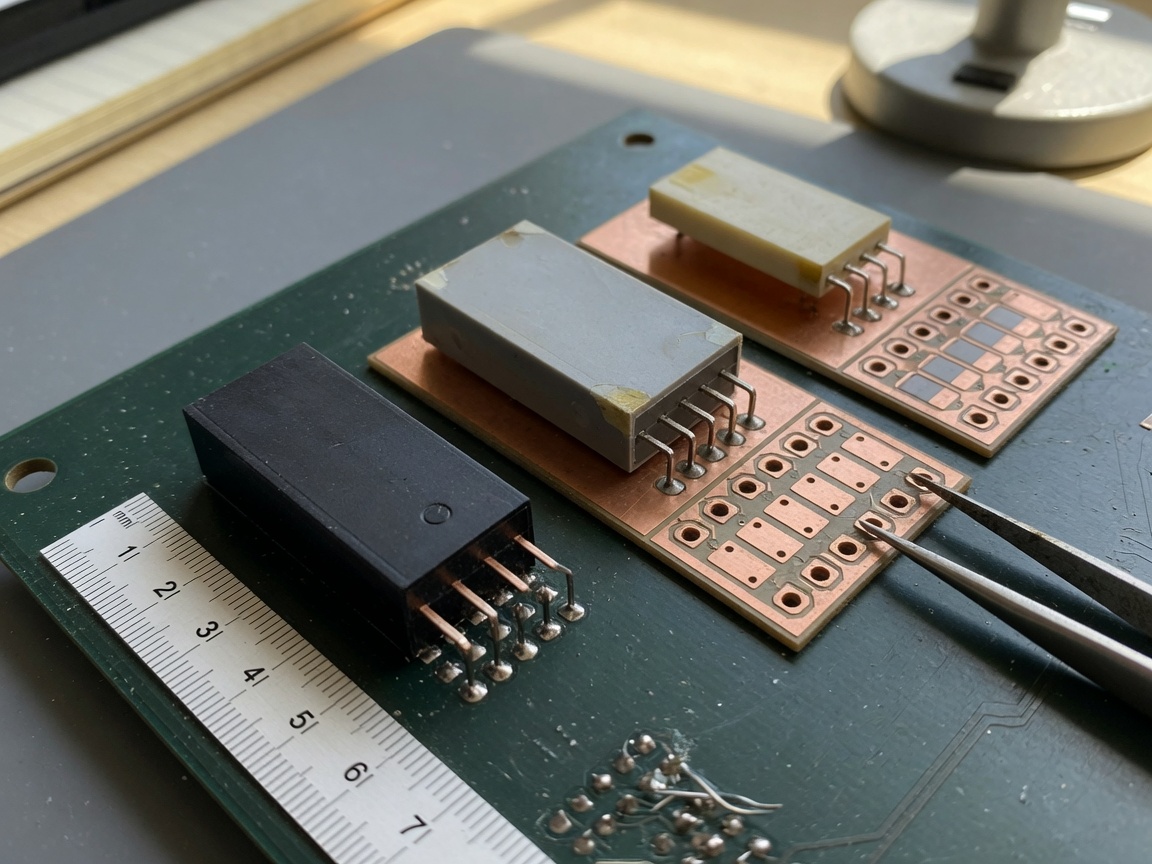
The SIL (single in-line) or MSIP (molded single in-line package) format places all pins in a single row, minimizing the PCB mounting width. Actual testing in multi-channel switching boards confirms that SIL designs allow roughly 40% more channels per unit area compared to DIP layouts of the same pitch. The molded overall frame design in modern SIL products also provides mechanical protection that loose glass-body relays cannot. For test engineers building 128-channel or 256-channel relay matrices, SIL is almost always the first choice. The VSIP series exemplifies this format with its compact single-column plug-in configuration.
DIP package: socketed reliability
The DIP reed relay is the go-to when field replaceability matters. Mounted in a standard IC socket, a failed relay can be swapped in under two minutes without soldering — a significant maintenance advantage in industrial control panels or medical devices that must pass re-qualification after any board modification. The dual in-line format also provides superior mechanical stability under vibration, which matters in mobile or rack-mounted equipment.
SMD package: maximum density
SMD (surface-mount) low profile relay packages like the VN series — with a footprint as small as 4.4 × 4.4 mm — enable board densities that simply are not achievable with through-hole parts. The trade-off is rework complexity. Once reflowed, SMD reed relays are difficult to replace without specialized hot-air equipment. For high-volume production with stable designs, SMD is compelling. For prototyping environments or serviceable field units, through-hole packages are more practical.
Key specifications explained
Specs on a reed relay datasheet can be deceptively simple. Four numbers — coil voltage, coil resistance, switching voltage, switching current — do not tell the full story. Here is what experienced designers actually pay attention to.
Coil power and operate/release voltage
The coil power consumption of a compact electromagnetic relay determines thermal density in multi-channel boards. Low power relay designs typically draw 50–140 mW per channel. Operate voltage is the minimum coil voltage guaranteed to close contacts; release voltage is the maximum at which contacts are guaranteed to open. The ratio of release to operate voltage (typically 0.1–0.5) defines hysteresis — useful for latching-mode designs. A common design error is driving a 5 V coil from a 3.3 V logic rail without checking the operate voltage threshold.
Contact load ratings and insulation resistance
The normally open reed contact in most miniature signal relays is rated for switching loads from dry circuit (below 1 mA / 0.1 V) up to 0.5–1 A at 100–200 VDC. Insulation resistance in a properly sealed glass envelope relay typically exceeds 1010 Ω — that is 10 teraohms — making the magnetic reed sensor switch suitable for femtoampere-level measurement circuits. Critically, this spec degrades over time if the glass seal is compromised, which is why package integrity matters more than headline specs.
Application-specific guidance: ATE, medical, and telecom
Why do so many engineering guides stop at generic specs? Real design choices happen within specific application constraints. Here are three domains where the miniature reed relay excels — with concrete design guidance for each.
Automated test equipment (ATE)
In ATE switching matrices, hundreds of PCB mount relay channels must operate simultaneously with microsecond timing, sub-100 mΩ contact resistance, and billions of switching cycles over instrument lifetime. SIL reed relays are the dominant choice because their single-row footprint allows high-density matrix wiring. Based on real cases from semiconductor test floor deployments, designers should: (1) derate contact load to under 20% of rated maximum, (2) implement per-row magnetic shielding to prevent crosstalk in adjacent channels, and (3) specify relays with operate times under 0.5 ms for high-throughput scan applications. The VSIP and MSIP series products with contact form 1A (SPST-NO) are standard selections for signal-level matrix switching.
Medical instrumentation
Patient-connected medical devices impose strict isolation requirements — often 1,500 V or higher between signal paths. High-voltage glass envelope relay variants (such as the HVMR series) support dielectric strength above 1,000 V between contacts, with insulation resistance above 10 TΩ. In ECG front-end switching, where the signal relay must not introduce noise floors above 1 µV, the sealed construction eliminates the particulate contamination that open-contact relays suffer over time. Equally important: sealed reed relays can be cleaned with standard PCB wash processes, simplifying IPC-compliant manufacturing.
Telecom signal switching
Telecom switching matrices demand consistent insertion loss and isolation over millions of daily operations. Reed relays optimized for RF performance — such as mercury-wetted variants (HGMR series) or shielded low-resistance designs — provide insertion loss below 0.1 dB at frequencies up to several hundred MHz. The external magnetic shielding and grounding pin featured on HGMR-type relays directly suppress interference between adjacent channels in a dense switching chassis. When designing telecom crosspoint matrices, DIP reed relays in socketed configurations allow hot-swappable maintenance without signal interruption on neighboring channels.
Coil drive circuit design essentials
Getting the coil drive circuit right is where many hardware engineers spend less time than they should. The relay itself may be flawless; a poorly designed driver will degrade it quickly or cause erratic operation.
Flyback diode selection
When a reed relay coil is de-energized, the collapsing magnetic field generates a voltage spike that can reach 10–100× the supply voltage. This transient destroys driver transistors and corrupts digital logic. The solution is a flyback diode placed in reverse bias across the coil terminals. Use a fast-recovery diode (1N4148 or BAV99 for 5 V systems) rather than a standard 1N400x rectifier — the slower recovery of power diodes extends the coil release time by 20–40%, degrading switching speed. For 12 V coil designs driving inductive loads, a TVS diode rated at 15–18 V clamps the spike more aggressively while maintaining acceptable release time.
"The flyback transient from an improperly protected reed relay coil can exceed 150 V on a 5 V rail — sufficient to latch-up CMOS logic or permanently degrade gate oxide in driver FETs. Diode selection is not optional; it is a fundamental reliability requirement."
— Based on application engineering best practices widely cited in power electronics design literature, 2026
PWM driving for power reduction and latch mode
A low power relay coil can be operated in two-stage drive mode: apply full voltage for the operate period (typically 5–10 ms), then reduce to 30–50% via PWM to maintain contact closure. This technique cuts per-channel power dissipation by up to 60%, directly enabling higher channel density without thermal management problems. Some reed relay designs support latch mode operation — a brief pulse closes the contacts, and they remain closed without continuous coil power due to a permanent magnet bias integrated into the assembly. Latch mode is ideal for battery-powered instruments where standby power is critical.
A step-by-step approach to coil driver design:
- Determine coil voltage and resistance from the datasheet; calculate steady-state coil current (I = V/R).
- Select a driver transistor or MOSFET with VCE(sat) or RDS(on) low enough to keep the coil voltage within operate threshold.
- Add a flyback diode (fast-recovery type) directly across coil pins, as close to the relay as possible.
- If using PWM, set the frequency above 10 kHz to prevent audible noise from the coil; start at 40% duty cycle and verify contact closure with an oscilloscope probe on the switched signal path.
- Measure operate and release times under real load conditions — datasheet values assume nominal voltage and room temperature.
- Verify that crosstalk between adjacent coil drivers does not produce false triggers on neighboring channels.
Failure modes and in-circuit testing
Reed relay failures are not random — they follow predictable patterns tied to load conditions, drive circuit quality, and environmental stress. Knowing these patterns lets engineers design for reliability rather than just replace failed parts.
Common failure causes
Contact sticking is the most frequently reported failure in overloaded reed relays. When switching currents exceed rated levels — even momentarily — resistive heating at the contact weld point can fuse the normally open reed contacts together. The result is a relay that closes normally but never opens. This failure is catastrophic in multiplexed switching because it creates a permanent short across the switched path. Always derate contact load to 50% or less of the rated maximum for continuous operation.
Coil burnout occurs when supply voltage exceeds rated coil voltage for extended periods, or when the coil is energized without the flyback diode and the resulting transients break down the coil insulation. Coil resistance will read open (infinite) on a multimeter. Insulation resistance degradation is more insidious — the glass envelope seal develops micro-cracks under thermal cycling or mechanical shock, allowing moisture ingress. Contact leakage current rises from picoamperes to nanoamperes, corrupting precision measurements long before the relay fails completely. This is why sealed reed relays from reputable manufacturers maintain glass-to-metal seals rated for –55°C to +125°C operation.
How to test reed relays in-circuit
In-circuit testing of a DIP reed relay or SIL package part follows this sequence. Measure coil resistance with power off — a value within ±10% of the datasheet spec confirms the coil is intact. Apply rated coil voltage and measure contact resistance with a four-wire (Kelvin) measurement; values above 500 mΩ on a new relay indicate contamination or contact damage. To test insulation resistance, apply 100 VDC between contact pins with coil de-energized and measure leakage; values below 109 Ω suggest seal failure. Of course, some in-circuit environments make four-wire contact resistance measurement impractical — in those cases, functional testing with a known-good signal path remains the most reliable approach.
RoHS and AEC-Q200 compliance for U.S. buyers
Compliance requirements are not just paperwork. For engineers sourcing miniature reed relays for U.S. markets in 2026, two standards directly affect supplier qualification.
RoHS compliance
RoHS 3 (EU Directive 2015/863) restricts ten hazardous substances in electronic components. Most modern sealed reed relays from established manufacturers are fully RoHS-compliant, using lead-free terminations and halogen-free molding compounds. When evaluating suppliers, request the RoHS declaration of conformity and verify that it covers the specific part number — not just a product family. Mercury-wetted reed relays (HGMR series) are explicitly exempted from certain RoHS restrictions for professional and industrial applications, but this exemption requires documented justification in the end-product compliance file.
AEC-Q200 and automotive/industrial qualification
AEC-Q200 is the automotive component stress test qualification standard developed by the Automotive Electronics Council. It covers temperature cycling, mechanical shock, vibration, moisture resistance, and electrical endurance. A miniature reed relay claiming AEC-Q200 compliance has passed standardized stress tests that typical commercial-grade parts have not. For U.S. automotive OEM supply chains — or industrial applications demanding equivalent reliability — specifying AEC-Q200 qualified parts reduces field failure risk significantly. Practically, this means verifying whether the supplier's test data covers the specific package and coil voltage variant, since qualification is part-number specific, not blanket across a product line.
How to choose the right miniature reed relay
After reviewing packages, specs, applications, driver design, and compliance, the selection decision should be systematic rather than intuitive. Here is a practical decision framework used in real procurement evaluations.
Selection decision framework
Start with application constraints: What is the maximum PCB area per channel? What coil voltage does your system supply? What is the switched signal's maximum voltage and current? These three parameters immediately filter the viable package formats and contact ratings. A 3.3 V system logic rail eliminates 12 V coil relays unless a boost converter is added — an unnecessary complication. A 200 V measurement path requires high-voltage glass envelope relay variants, not standard signal relays.
Consider channel density next. If you need over 64 channels on a single board, SMD or SIL packages are the only realistic choices. Below 16 channels in a serviceable field instrument, DIP in sockets gives better long-term maintainability. Finally — and this is a point competitors rarely mention — verify that your chosen supplier can provide ATE correlation data showing actual operate/release timing distributions across production lots. Relay-to-relay timing variation matters in synchronized multi-channel switching, and datasheet typical values do not capture lot-to-lot spread.
2026 market trends shaping selection criteria
Two forces are reshaping miniature reed relay selection in 2026. First, the semiconductor test equipment boom is driving demand for ultra-high-density relay modules — engineers are now specifying SMD reed relays at sub-5 mm pitch to build 512-channel switching cards that would have required multiple boards just five years ago. Second, the proliferation of 5G infrastructure equipment and new-energy vehicle battery management systems is pushing demand for relays with sub-milliwatt standby power and verified EMI performance. Low profile relay products with integrated magnetic shielding are becoming standard requirements in these applications, not optional upgrades. Sourcing from suppliers who can demonstrate both RoHS compliance and production-level reliability data will be the baseline expectation for serious U.S. buyers throughout 2026 and beyond.
Frequently asked questions
Q: What is the difference between a SIL and DIP miniature reed relay?
A: A SIL relay has all pins in a single row, giving a narrower PCB footprint ideal for high-channel-density ATE matrices. A DIP relay has two parallel pin rows, offering better mechanical stability and easy socketing for field replacement. DIP packages generally have a larger footprint but are preferred when serviceability is a priority.
Q: Do miniature reed relays require a flyback diode?
A: Yes. All inductive coil devices generate a voltage spike when de-energized. Without a flyback diode, this transient can destroy the driver transistor and corrupt nearby logic. Place a fast-recovery diode (1N4148 or equivalent) in reverse bias directly across the coil pins, as close to the relay as possible.
Q: How many switching cycles can a miniature reed relay handle?
A: Under signal-level loads (below 10 mA, below 10 V), high-quality sealed reed relays are rated for over one billion (10⁹) switching cycles. Operating at higher loads significantly reduces life. Derating contact load to 50% or less of rated maximum is the standard practice for maximizing operational lifespan in ATE and instrumentation applications.
Q: Are miniature reed relays RoHS compliant?
A: Most modern PCB mount reed relays from established manufacturers are fully RoHS 3 compliant, with lead-free terminations and halogen-free molding. Mercury-wetted types have specific exemptions for professional use. Always request a part-number-specific RoHS declaration, not a general product family statement.
Q: Can a miniature reed relay be used in medical devices?
A: Yes, sealed reed relays are widely used in medical instrumentation for ECG switching, patient isolation, and diagnostic equipment. High-voltage variants (such as HVMR series) support dielectric strength above 1,000 V between contacts. Their hermetically sealed glass envelope construction resists contamination during PCB washing, simplifying IPC-compliant medical device manufacturing.
Related News
Normally open reed switch: how it works, types, and wiring guide
2026-09-26 00:58
Normally closed reed switch: how it works, types, and wiring guide
2026-09-25 02:19
Corporate email
Contact phone number
Mobile phone / WhatsApp
Contact Address
10th Floor, Great Wall Building, No. 3000 Zhongshan North Road, Putuo District, Shanghai

Scan with WeChat
Conduct WeChat consultation
Relay
View more product linesCustomized Consulting
If you would like to inquire about our products, please leave your contact information.
We will contact you within 24 hours.




