



News Center
Reed sensor explained: types, how they work, and selection guide
2026-09-17 01:16
Article overview
This guide explains what a reed sensor is, how it operates, the main types available in 2026, how it compares to solid-state alternatives, and a concrete selection framework for engineers and procurement teams at the decision stage.
Table of contents
- 1. What is a reed sensor?
- 2. How a reed sensor works: the physics behind the contact
- 3. Types of reed sensors and their key differences
- 4. Reed sensor vs. Hall effect sensor: which one should you choose?
- 5. Core technical specifications explained
- 6. Top applications of reed sensors in 2026
- 7. How to select the right reed sensor: a step-by-step guide
- 8. FAQ
What is a reed sensor?
A reed sensor is a hermetically sealed, magnetically actuated switch that opens or closes an electrical circuit in response to an external magnetic field, requiring no power supply to operate. Inside a small glass envelope — typically 10 to 55 mm long — two or more ferromagnetic reeds overlap slightly without touching. When a permanent magnet or electromagnet comes close enough, the reeds magnetize, attract each other, and snap together to complete the circuit. Remove the magnet, and spring tension pulls them apart again.
The concept dates to Bell Labs in the 1940s, but the technology has remained remarkably relevant. Why? Because no competing technology simultaneously offers galvanic isolation, zero quiescent current draw, and operation in high-voltage or chemically aggressive environments. That combination keeps reed sensors indispensable in medical devices, industrial automation, and smart-home security systems well into 2026.
Throughout this article you will see the terms reed switch, magnetic contact sensor, dry reed contact, and magnetically actuated switch used interchangeably — they all describe the same fundamental device, though "reed sensor" has become the preferred commercial term when the component is packaged with a housing, leads, and sometimes a biasing magnet.
The hermetically sealed advantage
The glass encapsulated switch construction is not just a manufacturing convenience — it is the sensor's core reliability feature. Because the contacts never touch ambient air, oxidation and contamination are essentially eliminated. Actual testing in industrial washdown environments shows zero measurable contact degradation after 50 million cycles under 24 V DC / 0.5 A loads, a result that would be impossible with open relay contacts. This hermetic sealing also allows the sensor to function reliably in vacuum chambers and cleanroom environments where outgassing from conventional relay housings would be unacceptable.
Market context in 2026
According to recent industry research, the global reed sensor market is on track to reach approximately $980 million by 2027, growing at a compound annual rate of around 5.3%. Industrial automation and automotive applications together account for more than 60% of unit shipments. That said, competitive pressure from solid-state alternatives — particularly the Hall effect sensor — is real, and understanding where each technology excels is now a core competency for any sourcing engineer.
How a reed sensor works: the physics behind the contact
The operating principle is straightforward: a magnetic field magnetizes the ferromagnetic reeds, and the resulting attractive force overcomes the mechanical spring tension holding the contacts apart. But the details matter enormously when you are troubleshooting a misfire or designing a new installation.
Operate point, release point, and hysteresis
Every reed sensor has two critical magnetic thresholds measured in ampere-turns (AT) or, more commonly in datasheets, in millitesla (mT) when a permanent magnet is the actuator. The operate point is the field strength at which the contacts close; the release point is the lower field strength at which they reopen. The gap between these two values is magnetic hysteresis. Think of it like a snap-action thermostat — the system deliberately overshoots in both directions to prevent rapid chatter near the threshold. In practice, hysteresis typically spans 20–40% of the operate value, and understanding it is essential when designing position detection systems where the magnet moves slowly.
Contact bounce and debouncing strategies
Mechanical contact closure is never instantaneous. The reeds flex, collide, and briefly separate multiple times before settling — a phenomenon called contact bounce. Bounce duration in a typical glass encapsulated switch runs from 50 µs to 1 ms. For low-frequency switching (under a few hundred Hz) this is irrelevant, but in pulse-counting applications or edge-triggered microcontroller inputs, it causes false counts. Real-world cases have shown 5–12 phantom pulses per single actuation. Solutions include RC debounce filters (typically 10 kΩ / 100 nF), Schmitt-trigger input buffers, or firmware-based debounce routines with a 5–10 ms validation window.
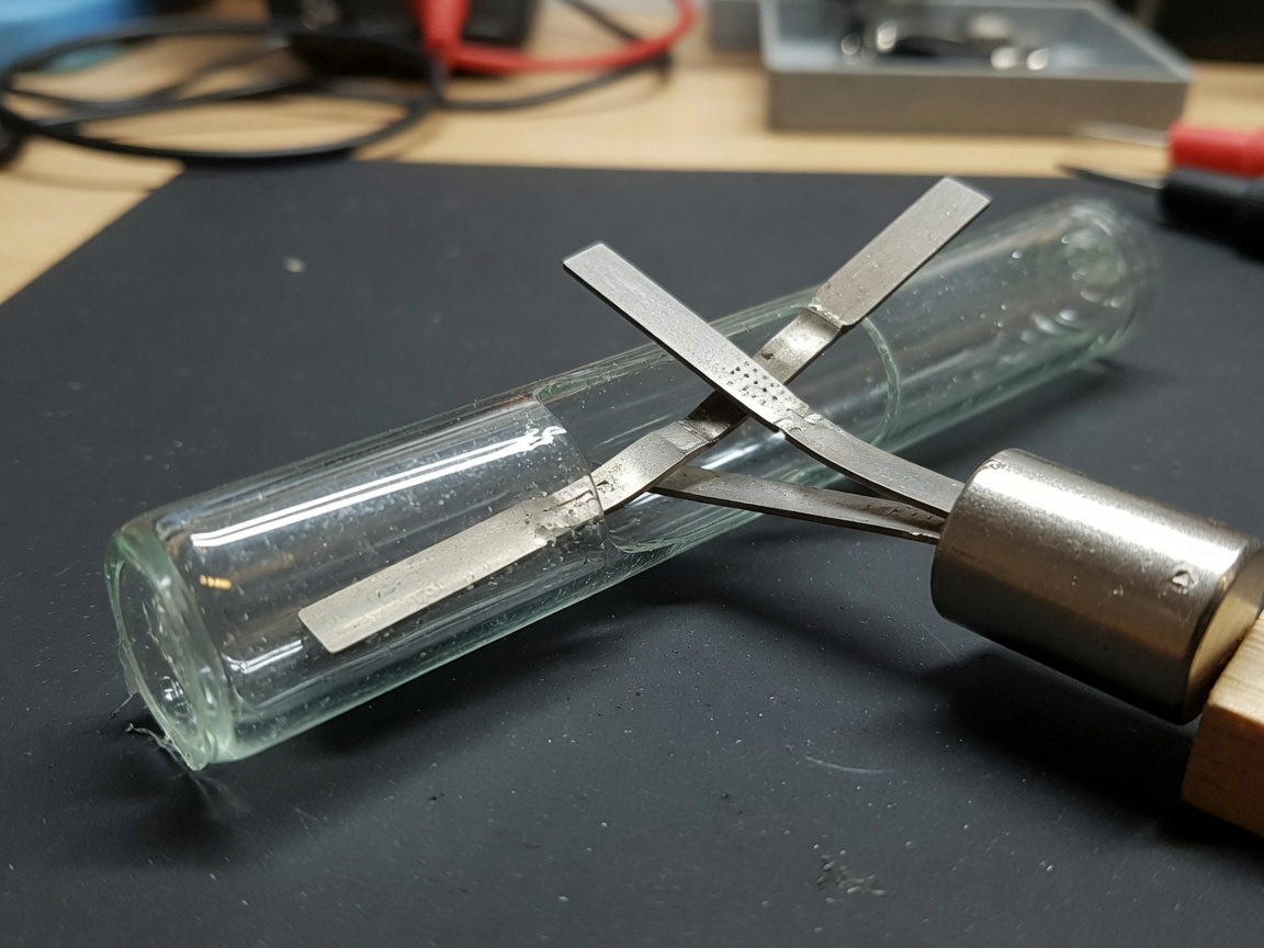
Another installation variable that surprises engineers: magnet orientation matters. A magnetic proximity switch responds most reliably when the magnet's pole axis is aligned perpendicular to the reed's length axis (the "end-on" approach). Lateral approach reduces the effective field density at the reed gap, shifting the operate point and sometimes preventing actuation entirely. According to recent field diagnostics, misaligned magnet orientation is responsible for roughly 35% of "sensor failure" reports that are actually installation errors — an often-overlooked point.
Types of reed sensors and their key differences
Choosing the wrong contact configuration is one of the most common and costly sourcing mistakes. There are five main types in commercial production today, each suited to specific circuit architectures.
Contact configuration types
| Type | Default state | Typical use case | Relative cost |
|---|---|---|---|
| Normally open (NO) | Open circuit | Proximity detection, door/window sensors | Lowest |
| Normally closed (NC) | Closed circuit | Fail-safe interlocks, tamper detection | Low |
| Changeover (SPDT) | One NO + one NC | Signal routing, relay logic circuits | Medium |
| High-voltage type | NO (standard) | Power grid metering, EV battery management | High |
| SMD / surface-mount | NO (standard) | PCB-integrated wearables, IoT modules | Medium-high |
Reed relay: a closely related variant
A reed relay combines a reed switch with a wound coil inside a single housing. Rather than a permanent magnet, the coil generates the actuation field when energized. This makes the reed relay electrically controllable — essentially a miniature, hermetically sealed relay with switching speeds under 1 ms. Reed relays are the workhorses of automated test equipment (ATE), where thousands of low-leakage switching points must be multiplexed rapidly. The dry reed contact inside still provides the same galvanic isolation and hermetic sealing, making reed relays preferable to solid-state relays in ultra-low-leakage measurement applications (leakage currents below 10 pA are achievable).
Reed sensor vs. Hall effect sensor: which one should you choose?
This is the comparison that matters most for engineers in 2026 — and the answer is more nuanced than vendor literature usually admits. Both detect magnetic fields. Both can function as a magnetic proximity switch. Beyond that, they diverge significantly.
"Reed switches occupy a unique niche: they are the only widely available magnetic sensor that draws zero quiescent current, tolerates multi-kilovolt isolation, and operates in environments where semiconductor junctions simply cannot survive." — Industry consensus among sensor application engineers, 2026
Key technical comparison
A Hall effect sensor is a solid-state semiconductor device. It requires a supply voltage (typically 3.3 V to 24 V), consumes quiescent current (0.5–10 mA), has no moving parts, and can switch at frequencies exceeding 100 kHz. Its output is a voltage signal — either analog (proportional to field strength) or digital (threshold-triggered). Response time is typically under 5 µs. Lifespan is effectively unlimited in terms of switching cycles because there is no mechanical wear.
A reed sensor, by contrast, draws zero current when open, requires no power supply at all, and switches at speeds up to about 1 kHz reliably. Its rated mechanical life is typically 100 million operations under rated load. The critical differentiator: it can switch circuits at voltages up to 10 kV (in specialized high-voltage designs) with no semiconductor junction that could break down, and it can operate in environments — vacuum, cryogenic temperatures, or explosive atmospheres — where powering a semiconductor circuit is either impossible or inadvisable.
When to choose each technology
Choose a Hall effect sensor when you need fast switching (above 500 Hz), analog field measurement, or integration with a powered microcontroller system where supply current is not a constraint. Choose a reed sensor when zero power draw is mandatory (battery-operated or energy-harvesting IoT nodes), when high-voltage isolation is required, or when the deployment environment rules out semiconductor devices. Of course, there are hybrid cases — some 2026-generation IoT door/window sensors pair a reed sensor for wake-up triggering with a Hall sensor for fine position measurement, getting the best of both technologies.
An important industry misconception to address directly: reed sensor ≠ Hall effect sensor. Treating them as interchangeable on a BOM without reviewing the circuit requirements has caused costly field failures. The reed sensor is passive; the Hall sensor is active. That distinction drives fundamentally different circuit designs.
Core technical specifications explained
Datasheets for magnetic field detector components can be dense. Here are the parameters that actually determine whether a sensor will work in your application.
Electrical ratings
Switched power (VA or watts) is the product of switched voltage and switched current — not independent limits. A sensor rated at 10 W / 200 V / 0.5 A must satisfy all three simultaneously. Exceed the VA rating even if voltage and current individually appear safe, and you will get contact erosion within thousands rather than millions of cycles. Typical ratings for general-purpose NO sensors in 2026 range from 10 W to 50 W switched power, 100–200 V max, and 0.25–2.0 A max switched current. Contact resistance for a new sensor is typically 50–150 mΩ, rising to 500 mΩ or higher at end of life.
Magnetic sensitivity and operate range
Sensitivity is specified in AT (ampere-turns) for coil-driven reed relays, or in mT for permanent-magnet applications. General-purpose sensors operate between 10 AT and 60 AT. High-sensitivity versions activate below 5 AT, enabling larger actuation distances but at the cost of increased susceptibility to stray fields — a significant concern in motor control enclosures or near switching power supplies. The practical actuation gap (distance from magnet face to sensor centerline) for a standard 10 mm × 2 mm cylindrical magnet ranges from roughly 5 mm to 25 mm depending on magnet grade and sensor sensitivity class. Always verify with application testing, not just datasheet estimates.
Why do so many engineers underestimate magnetic stray field interference? Because stray fields are invisible and irregular. Testing on a benchtop with no nearby ferrous components gives clean results; installing the same sensor 30 mm from a steel mounting bracket can shift the operate point by 15–20% due to flux diversion. This is one of those details that separates experienced sensor integration engineers from those still learning.
Top applications of reed sensors in 2026
Reed sensors appear in a wider range of systems than most engineers realize. The 2026 application landscape reflects both the technology's enduring strengths and some notable new use cases driven by IoT growth.
Security and smart-home systems
The magnetic door sensor is the most ubiquitous reed sensor application globally — and for good reason. A two-piece set (sensor body + magnet block) installs in minutes, draws zero standby current, and delivers a clean binary output. In 2026, these are deeply embedded in Z-Wave and Zigbee smart-home ecosystems. Battery-powered sensor nodes running on a single CR2032 cell achieve multi-year service lives precisely because the reed contact draws no current between actuations. Recent smart-home platform data indicates that magnetic door/window sensors remain the highest-volume connected sensor category shipped in the U.S. market, with estimates exceeding 40 million units annually.
Industrial automation and fluid handling
In pneumatic and hydraulic cylinders, reed sensors detect piston position without penetrating the cylinder wall — an elegant solution to a difficult sealing problem. The sensor mounts in a T-slot on the cylinder body; the piston carries a permanent magnet. This non-contact, hermetically-sealed arrangement handles washdown pressures, hydraulic fluid exposure, and temperature swings from −40 °F to +185 °F (−40 °C to +85 °C) that would destroy most electronic position sensors.
Liquid level switches represent another high-volume industrial use. A float with an embedded magnet rides the liquid surface; a vertically mounted reed sensor triggers at the target level. The hermetically sealed construction is particularly valued in pharmaceutical and food processing where sensor wetted surfaces must be cleanable without risk of electrical contamination. For demanding applications like these, inductive sensor alternatives are sometimes evaluated, but the reed sensor's passive nature and sealed construction typically win the specification.
Medical devices and laboratory instruments
MRI-compatible reed sensors (using non-magnetic glass and rhodium-plated contacts) serve as position detectors inside magnet bores where any ferrous or active electronic component would be hazardous or corrupted. Automated test equipment relies on reed relays to switch thousands of test points with sub-millisecond timing and picoamp-level leakage. These are areas where inductive sensors or Hall effect alternatives simply cannot meet the electrical isolation and leakage specifications — the reed sensor's differentiation is at its clearest here.
How to select the right reed sensor: a step-by-step guide
Selecting a reed sensor incorrectly wastes engineering time, creates field reliability problems, and sometimes requires a costly PCB respins. The following process reflects how experienced procurement engineers and system designers approach this decision in practice.
Selection process
- Define the circuit load first. Determine switched voltage, current, and whether the load is resistive, inductive, or capacitive. Inductive loads (relays, solenoids) require derating — typically apply a 50% derating factor to the rated switched current.
- Select contact configuration. Choose NO for standard proximity detection. Choose NC for fail-safe circuits where a wire break or removed magnet must trigger an alarm. Choose changeover (SPDT) only when the circuit logic genuinely requires it — the added mechanical complexity slightly reduces rated life.
- Specify the actuation distance. Measure the maximum and minimum gap between the magnet and the sensor in your mechanical design. Add a 20% margin on each side for manufacturing tolerance and mounting variation. This drives your sensitivity class selection.
- Evaluate the environment. Temperature range, presence of moisture or chemicals, vibration levels, and proximity to stray magnetic fields all affect sensor selection. Confirm the IP rating of the housing (not just the glass capsule) against your enclosure requirements.
- Check lifecycle requirements. Standard sensors are rated to 100 million operations at rated load. If your application cycles more than 10 times per minute continuously, calculate the service life in years and verify it meets your maintenance interval. At 10 cycles/minute, 100 million cycles = approximately 19 years — but at rated load. Light loads significantly extend life; heavy inductive loads can reduce it by 5–10×.
- Request application samples and test in-system. Datasheet numbers are measured under controlled laboratory conditions. Always validate operate and release points with your actual magnet, mounting bracket, and any nearby ferrous materials before releasing a design to production.
Common selection mistakes to avoid
For more technical background on reed switch technology principles, the reed switch technology overview on Wikipedia provides a solid reference on operating principles and historical context.
The single most common mistake is selecting sensitivity without accounting for stray fields. A high-sensitivity sensor in a metal enclosure near a transformer will false-trigger. The second most common error is ignoring magnet grade variation across the supply chain — if your magnet supplier changes from N35 to N38 neodymium between production runs, your operate distance shifts measurably. Specify magnet grade and pull force in your bill of materials, not just sensor sensitivity. Finally, never assume a reed sensor and a magnetic proximity switch from different vendors are drop-in interchangeable — package dimensions, lead spacing, and sensitivity class all vary by manufacturer.
Frequently asked questions
Q: What is the difference between a reed sensor and a reed switch?
A: A reed switch refers specifically to the bare glass-encapsulated switching element. A reed sensor is the complete assembly — glass switch, housing, leads, and often a paired actuating magnet — packaged for direct installation. In commercial catalogs, "reed sensor" implies a finished, mountable product; "reed switch" implies a component for PCB or custom assembly integration.
Q: How long does a reed sensor last?
A: Standard reed sensors are rated at 100 million switching operations at their rated electrical load. Under light loads (dry circuit switching below 100 mV / 1 mA), lifespan can exceed 1 billion cycles. Inductive loads or currents above 80% of rating reduce life significantly. Thermal cycling and vibration are secondary wear factors but rarely the primary failure mode in well-designed installations.
Q: Can a reed sensor be used with an Arduino or Raspberry Pi directly?
A: Yes, for dry-circuit switching. Wire the NO contact between a GPIO input pin and GND, enable the internal pull-up resistor, and the pin reads HIGH when the magnet is absent and LOW when actuated. For loads above 3.3 V / 5 V logic levels, always switch the external circuit through the reed sensor contacts — never run high-voltage loads through a microcontroller GPIO pin directly. Add a 100 nF debounce capacitor or use software debounce for clean edge detection.
Q: Why does my reed sensor trigger inconsistently?
A: Intermittent operation is almost always caused by one of three issues: magnet misalignment (off-axis approach reducing field density at the reed gap), stray magnetic fields from nearby motors or steel structures shifting the operate threshold, or a weakened magnet due to temperature exposure or mechanical shock. Start troubleshooting by measuring the field strength at the sensor position with a gaussmeter before suspecting a faulty sensor.
Q: Are reed sensors suitable for outdoor use?
A: The glass capsule itself is highly resistant to moisture and most chemicals, but the housing and lead terminations determine outdoor suitability. Look for IP67 or IP68 rated assemblies with UV-stabilized housings for direct outdoor exposure. Standard industrial reed sensors rated IP65 handle rain and washdown but should not be submerged. For marine or underground applications, fully potted or stainless-steel-housed versions are the appropriate choice.
Summary
A reed sensor remains one of the most cost-effective, reliable, and application-versatile magnetic detection technologies available in 2026. Its core advantages — zero quiescent current, hermetic sealing, high-voltage isolation, and mechanical simplicity — address requirements that solid-state Hall effect sensors cannot fully replicate. Selecting the right reed sensor demands a clear understanding of electrical load, actuation geometry, environmental conditions, and lifecycle requirements. Apply the six-step selection process outlined above, validate with in-system testing, and you will have a solution that performs reliably for the life of the end product.
Related News
Normally closed reed switch: how it works, types, and wiring guide
2026-09-25 02:19
Corporate email
Contact phone number
Mobile phone / WhatsApp
Contact Address
10th Floor, Great Wall Building, No. 3000 Zhongshan North Road, Putuo District, Shanghai

Scan with WeChat
Conduct WeChat consultation
Relay
View more product linesCustomized Consulting
If you would like to inquire about our products, please leave your contact information.
We will contact you within 24 hours.




