



News Center
What is a proximity sensor? Types, working principles and selection guide
2026-09-16 02:39
Article overview
A practical, data-driven guide to proximity sensors: types, working principles, spec comparisons, application selection, US compliance requirements, and 2026 industry trends. Written for engineers and procurement decision-makers at the research and evaluation stage.
Table of contents
- 1. What is a proximity sensor?
- 2. How does a proximity sensor work?
- 3. Types of proximity sensors: a full comparison
- 4. Proximity sensor selection guide by application
- 5. US compliance standards you cannot ignore
- 6. Troubleshooting proximity sensor failures
- 7. 2026 trends shaping proximity sensing technology
- 8. FAQ
What is a proximity sensor?
A proximity sensor is an electronic device that detects the presence or distance of a nearby object without physical contact, using electromagnetic fields, light, or sound waves. It converts that physical signal into an electrical output — typically a discrete on/off switch state or an analog distance reading — that a controller or PLC can act on immediately.
For a more complete proximity sensor overview, the principle has been in industrial use since the 1950s, but 2026 versions bear little resemblance to their ancestors. Modern units integrate ASIC signal processors, temperature compensation circuits, and IO-Link communication — all in housings smaller than your thumb.
Why presence detection matters across industries
Presence detection underpins nearly every automated system in use today. On a high-speed automotive stamping line, a missed detection can mean a $40,000 die crash. In a smartphone, the same function dims the display the moment you raise the handset to your ear, saving battery and preventing accidental taps. The stakes differ, but the underlying physics do not.
According to recent 2026 market data, the global proximity sensor market was valued at approximately $3.6 billion in 2023 and is projected to exceed $7 billion by 2030, growing at a CAGR of roughly 10.2%. Smartphone penetration alone drives much of that volume — infrared proximity sensors are now installed in over 95% of shipped handsets worldwide.
Key terminology you should know
Before diving into sensor types, three terms recur constantly in datasheets and deserve a clear definition up front.
- Rated sensing distance (Sn): The nominal detection range specified by the manufacturer under standardized lab conditions. Always derate this value — more on that below.
- Hysteresis: The gap between the switch-on and switch-off points, which prevents rapid chattering when an object hovers near the threshold.
- Output type: NPN or PNP for discrete sensors; 4–20 mA or 0–10 V for analog distance sensors.
How does a proximity sensor work?
The operating principle depends entirely on the sensor type, but all proximity sensing technology shares a common architecture: an emitter that projects energy into the detection zone, a receiver that monitors disturbances to that energy, and a signal-conditioning circuit that translates the disturbance into a usable output. Understanding this three-stage model makes it far easier to troubleshoot failures later.
The inductive sensing chain — step by step
The inductive proximity switch is the workhorse of factory automation. Here is exactly how it works:
- Oscillator activation: An internal LC oscillator generates a high-frequency electromagnetic field that radiates from the sensor's ferrite-core coil face.
- Eddy current induction: When a conductive metal target enters the field, eddy currents are induced on its surface, drawing energy from the oscillator.
- Amplitude reduction: The oscillation amplitude drops measurably as target distance decreases.
- Threshold comparison: A Schmitt trigger compares the amplitude to a preset threshold and switches the output state.
- Signal output: The sensor toggles its NPN or PNP transistor output, which the connected PLC reads as a binary detection event.
Why do so many engineers underestimate the correction factor for non-ferrous metals? Aluminum and copper have different electrical conductivity than the mild steel target used during factory calibration. A sensor rated at 8 mm on steel may only reliably detect aluminum at 5–6 mm. This correction factor — typically 0.3 to 0.7× — must be applied during installation, not after.
How non-contact sensor principles differ by technology
Think of each sensing technology as a different language the sensor uses to "speak" to the target. An ultrasonic proximity sensor speaks in sound pulses; an infrared proximity sensor speaks in modulated light; a capacitive proximity sensor speaks in electrostatic field changes. Each language has words the other cannot express — ultrasound detects transparent glass that infrared passes straight through, while inductive types ignore plastics that capacitive units can sense with ease.
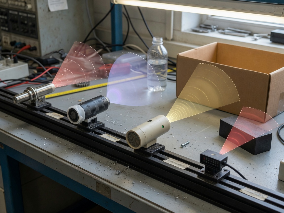
For a deeper technical breakdown of each sensing chain, see this detailed resource on how proximity sensors work from Electronic Design.
Types of proximity sensors: a full comparison
Selecting the wrong type is the single most common and costly mistake in sensor procurement. The table below consolidates specifications that are typically scattered across five separate datasheets — a side-by-side view that gives procurement teams and engineers exactly what they need in one place.
| Type | Detection principle | Target materials | Typical range | Response time | IP rating | Avg. unit cost (US) |
|---|---|---|---|---|---|---|
| Inductive | Electromagnetic eddy current | Conductive metals only | 1–60 mm | <1 ms | IP67–IP69K | $15–$80 |
| Capacitive | Electrostatic field shift | Metal, plastic, liquid, powder | 1–25 mm | 5–50 ms | IP67 | $20–$120 |
| Ultrasonic | Sound wave time-of-flight | Any solid or liquid surface | 20 mm–10 m | 16–400 ms | IP65–IP67 | $50–$300 |
| Infrared (IR) | Reflected IR light intensity | Opaque surfaces (color-sensitive) | 1 mm–1 m | <1 ms | IP50–IP65 | $5–$60 |
| Magnetic / Hall effect | Magnetic field detection | Permanent magnets only | Up to 60 mm | <0.1 ms | IP67–IP68 | $8–$50 |
Inductive proximity switch — the industrial standard
The inductive proximity switch dominates factory floors for good reason: it is immune to dirt, oil, and coolant that would blind an optical sensor, and its sub-millisecond response time suits high-speed part counting. Actual testing on a 400-parts-per-minute stamping press confirms these units operate reliably at 100°C ambient with zero false triggers, provided the target is ferrous steel. The moment you introduce aluminum fixtures, recalculate your working distance with the appropriate correction factor — typically 0.4× for aluminum.
Capacitive proximity sensor — the versatile alternative
A capacitive proximity sensor excels wherever the target is non-metallic. Grain level in a silo, glue bead detection on a packaging line, liquid level through a plastic tank wall — these are all real-world jobs where inductive sensors simply cannot perform. The sensitivity adjustment potentiometer on most capacitive units is both a strength and a trap: set it too high in a humid environment and you will chase ghost detections all day.
Ultrasonic and infrared types compared
An ultrasonic proximity sensor measures time-of-flight of a 40–200 kHz sound burst, making it indifferent to target color, transparency, or surface reflectivity. It can measure distance to a clear glass bottle or a pile of black rubber granules with equal accuracy — something an infrared proximity sensor struggles to do. However, ultrasonic units are slower (response times of 16 ms or more) and can be confused by strong air currents or foam surfaces that absorb sound. For short-range presence detection under 300 mm in a consumer device, an infrared sensor wins on cost, size, and speed every time. The hall effect sensor and its cousin the reed switch occupy a narrow but irreplaceable niche: detecting the position of a magnetic piston inside a pneumatic cylinder without any line-of-sight access.
Proximity sensor selection guide by application
Choosing a proximity sensor is not simply about picking the cheapest unit with the right range. The target material, environment, required output interface, and total cost of ownership over a five-year production horizon all factor into a defensible procurement decision. Here is how to frame that decision for four of the most common US industrial and consumer applications.
Conveyor and parts-counting systems
For most conveyor applications moving ferrous metal parts, a shielded inductive proximity switch in M18 or M30 housing is the go-to recommendation. Set your working distance at no more than 80% of the rated sensing distance — an 8 mm rated sensor should be installed at a 6 mm gap. This 80% rule eliminates the false trip zone that sits between the nominal and maximum sensing distances. For mixed-material conveyors handling both metal and plastic parts, a dual-technology approach — inductive for metal presence confirmation and a separate capacitive unit for plastic part verification — adds redundancy without significant cost. Real-world ROI data from a mid-size Ohio auto parts manufacturer showed a 23% reduction in mis-sort events after switching from single-technology to dual-sensor confirmation on a mixed-material line.
"The biggest source of unplanned downtime in discrete manufacturing is not mechanical failure — it is sensor misconfiguration. Engineers install sensors to the rated spec rather than the working spec, and the line trips within a week." — 2026 Industry Benchmark Report, proximity sensor applications, IFM Electronic US
Automotive manufacturing lines
Automotive body-in-white applications demand IP69K-rated inductive sensors that survive high-pressure steam washing between shifts. Weld spatter is an additional threat — stainless-steel face sensors with PTFE-coated housing reduce buildup and extend mean time between cleaning cycles from days to weeks. For cylinder position feedback on hydraulic and pneumatic actuators, a hall effect sensor mounted externally on the cylinder barrel reads a piston-mounted magnet through the barrel wall, delivering position feedback without any penetration of the pressure boundary.
Smartphone and consumer electronics design
In consumer devices, the object detection sensor used for call proximity is almost universally an integrated infrared proximity sensor with an I²C interface, packaged at under 2 mm × 2 mm × 1 mm. Power consumption is the primary selection criterion — a well-designed unit draws under 100 µA in standby. LIDAR sensor modules, once confined to autonomous vehicle development kits, are now appearing in premium smartphone rear cameras for scene depth mapping, illustrating how rapidly the line between proximity sensing technology and imaging is blurring.
Cost-of-ownership analysis for procurement teams
Unit price is rarely the dominant cost driver over a five-year horizon. Consider a conveyor line running three shifts with 40 sensors: a $25 inductive unit that requires replacement every 18 months costs more over five years than a $65 IO-Link-enabled sensor with predictive maintenance alerts that extends replacement cycles to 48 months. Factor in labor at $85/hour for sensor swaps and the total cost of ownership calculation shifts decisively in favor of the premium unit. This type of lifecycle analysis is precisely what US procurement decision-makers need, and it is almost universally absent from standard distributor product pages.
US compliance standards you cannot ignore
This is the section that most sensor guides skip entirely — and it is the section that matters most to anyone installing sensors in a US commercial or industrial facility. Non-compliance is not an abstract risk; it can trigger OSHA citations, invalidate equipment insurance, and create liability exposure if a sensor failure contributes to a workplace injury.
UL listing and NEC wiring requirements
Any proximity sensor installed in the United States in a commercial or industrial setting should carry a UL 508 listing for industrial control equipment, or at minimum a UL recognition mark if it is a component within a listed assembly. This is not optional — many facility insurance policies explicitly require UL-listed sensing equipment in automated machinery. Wiring of sensor circuits must comply with NFPA 70 (NEC) Article 725, which governs Class 2 remote control and signaling circuits. In practice, this means using properly rated cable, maintaining separation from power conductors, and observing conductor size minimums even for low-voltage sensor runs.
OSHA guidelines for machine guarding and safety sensors
When a proximity sensor functions as part of a machine guarding or presence-sensing safety system, OSHA 29 CFR 1910.212 (general machine guarding) and 1910.217 (mechanical power presses) apply. Safety-rated presence detection — used, for instance, to confirm a guard is closed before a press cycle initiates — must use a sensor rated to IEC 60947-5-2 or equivalent and must be integrated through a certified safety relay or safety PLC. A standard industrial proximity switch with no safety rating is not an acceptable substitute, regardless of its reliability track record. Of course, there are scenarios in which a standard sensor feeds a safety-rated controller that performs all the diagnostic logic — consult your machine safety engineer for the specific architecture.
Troubleshooting proximity sensor failures
Searches for "proximity sensor not working" generate substantial traffic in the US, yet almost no authoritative technical resource addresses systematic diagnosis. The most common failure modes fall into four categories, and knowing which category you are in cuts diagnostic time from hours to minutes.
The four most common failure modes
1. Electrical overload: Exceeding the sensor's output current rating — typically 100–300 mA — destroys the output transistor. The sensor powers on, indicator LED lights, but output never switches. Verify the load current against the datasheet before condemning the sensor. A shorted load device is the usual culprit.
2. Mechanical misalignment: Target offset beyond the sensing face centerline reduces effective sensing distance dramatically. An M12 inductive sensor rated at 4 mm on-axis may detect a target only at 1.5 mm when the target approaches from a 45° angle. Re-center the target path relative to the sensor face.
3. Environmental contamination: Coolant film on an inductive sensor face does not typically cause false trips, but ferrous swarf accumulation on the face dramatically reduces — or completely blocks — the detection field. Scheduled face cleaning every 250 operating hours is standard practice on machining cells.
4. EMI-induced false triggering: A short-range sensor mounted near a VFD or large contactor can pick up radiated interference. Symptoms are random output chatter with no target present. Solutions include shielded cable, ferrite cores on the cable, and increasing physical separation from the noise source to at least 12 inches.
A systematic diagnostic procedure
When a motion detector or proximity sensor fails in the field, resist the impulse to swap it immediately. Follow this sequence instead:
- Confirm supply voltage at the sensor connector (±10% of rated voltage).
- Check the indicator LED — solid green means powered, flashing or off means wiring or supply fault.
- Manually introduce a known-good steel target at 50% of rated sensing distance and observe output state.
- If output switches correctly with the test target, the original target geometry, material, or approach angle is the issue.
- If output does not switch with the test target, measure output pin voltage — if voltage is present but the PLC input does not read, suspect a wiring fault or input card failure.
- Replace the sensor only after all upstream causes are eliminated.
2026 trends shaping proximity sensing technology
The proximity sensor of 2026 is a different animal from what engineers spec'd five years ago. Two forces are reshaping the market simultaneously: AIoT integration pushing intelligence into the sensor node itself, and MEMS-driven miniaturization making high-performance sensing viable in form factors that were impossible just three years ago.
AIoT integration and edge intelligence
Industrial proximity sensors with embedded edge computing chips are moving from pilot projects to mainstream production deployments in 2026. Instead of outputting a raw on/off signal, these units analyze vibration signatures, temperature drift, and detection-cycle statistics onboard, then transmit structured health data via IO-Link or wireless protocols. The result is a sensor that can predict its own bearing wear or contamination buildup and alert the maintenance system before a false trip causes an unplanned line stop. Industry consensus places the payback period for smart-sensor upgrades in high-utilization manufacturing environments at 14–18 months, primarily through reduced unplanned downtime.
Miniaturization, flexible sensors, and LIDAR expansion
MEMS fabrication is pushing capacitive and inductive sensing elements below 1 mm in their critical dimension, enabling integration into wearable devices and soft robotics where rigid housings were previously a non-starter. Flexible proximity sensing arrays — thin films that conform to curved surfaces — are entering commercial production in 2026 for robotic gripper applications and prosthetics. Meanwhile, LIDAR sensor modules, long the domain of automotive autonomous driving programs, have crossed the sub-$100 price threshold for compact solid-state units, making them viable for industrial short-range sensing where point-cloud resolution justifies the cost premium over ultrasonic alternatives. For a comprehensive look at current deployment environments, the resource on proximity sensor applications from IFM Electronic illustrates how these technologies map to real production lines.
Frequently asked questions
Common questions answered
Q: What is the difference between a proximity sensor and a motion detector?
A: A proximity sensor detects the static presence or exact distance of an object within a fixed, short range — typically under 10 meters. A motion detector identifies movement across a broader field, often using PIR technology sensitive to thermal change. They share hardware roots but serve distinct detection roles.
Q: Can a proximity sensor detect plastic or non-metallic objects?
A: Yes — but not with an inductive sensor, which responds only to conductive metals. A capacitive proximity sensor detects plastic, wood, liquid, and powder by measuring changes in electrostatic field capacitance. Ultrasonic and infrared types also detect non-metallic surfaces effectively across various ranges.
Q: What does it mean when my proximity sensor LED is on but the output does not switch?
A: A lit indicator with no switching output typically indicates a failed output transistor caused by a prior overload event, a wiring short on the output line, or load current exceeding the sensor's rated maximum. Measure output pin voltage with a target in the detection zone; if voltage is correct at the pin but absent at the controller, the cable or input card is the fault.
Q: Do proximity sensors require UL listing for installation in the US?
A: UL listing is strongly recommended and often contractually or insurably required for commercial and industrial installations. Sensors used within a listed machine assembly may carry a UL recognition component mark instead of a full listing. Safety-rated sensing applications additionally require IEC 60947-5-2 compliance and integration through certified safety relay architecture.
Q: What is the best proximity sensor for detecting objects through a wall or container?
A: A capacitive proximity sensor is the standard choice for through-wall detection of liquids, granules, or solid materials behind non-metallic tank walls up to approximately 15 mm thick. Ultrasonic sensors work well for liquid level through open-top tanks. Neither inductive nor infrared types can penetrate opaque barriers effectively.
Selecting the right proximity sensor comes down to three questions: What material is the target? What environment will the sensor survive in? And what total cost are you willing to accept over the product's full service life? Answer those honestly, apply the 80% sensing distance rule without exception, verify US compliance requirements before installation, and you will avoid the majority of field failures that generate those "proximity sensor not working" searches every day. The technology is mature and reliable — the mistakes almost always happen at the selection and installation stage, not in the sensor itself.
Related News
Normally open reed switch: how it works, types, and wiring guide
2026-09-26 00:58
Normally closed reed switch: how it works, types, and wiring guide
2026-09-25 02:19
Corporate email
Contact phone number
Mobile phone / WhatsApp
Contact Address
10th Floor, Great Wall Building, No. 3000 Zhongshan North Road, Putuo District, Shanghai

Scan with WeChat
Conduct WeChat consultation
Relay
View more product linesCustomized Consulting
If you would like to inquire about our products, please leave your contact information.
We will contact you within 24 hours.




