



News Center
Surface mount reed switch: how to choose and install the right one for your project
2026-09-16 01:18
Article overview
This guide is written for PCB design engineers and procurement teams evaluating surface mount reed switches in 2026. It covers component types, a consolidated spec comparison table, magnet pairing guidance, reflow soldering parameters, orientation sensitivity on PCB layouts, and annotated application circuits — content gaps that nearly every competing article leaves unaddressed.
Table of contents
- 1. What is a surface mount reed switch?
- 2. SMD reed switch types and contact configurations
- 3. Side-by-side specification comparison table
- 4. Magnet actuation distance and field strength guidance
- 5. Reflow soldering compatibility and MSL ratings
- 6. PCB layout and orientation sensitivity
- 7. Real-world application circuits
- 8. 2026 trends and selection checklist
- 9. FAQ
What is a surface mount reed switch?
A surface mount reed switch is a hermetically sealed, magnetically actuated electromechanical switch designed to be soldered directly onto a PCB surface without through-hole leads. Inside the glass capsule, two overlapping ferromagnetic reeds sit in a sealed inert-gas environment. When an external magnetic field of sufficient strength passes through the capsule, the reeds deflect, make contact, and complete a circuit. Remove the field, and the reeds spring back open.
Why does this matter to a PCB design engineer? Because the SMD form factor eliminates manual lead-forming, cuts board real estate by roughly 60% compared to axial through-hole equivalents, and integrates seamlessly into standard pick-and-place and reflow assembly lines. According to recent 2026 market data, the global reed switch market is on track toward $420 million by 2027, with the SMD segment capturing a growing share as IoT and wearable device production scales up.
Understanding reed switch technology at a fundamental level — how the glass envelope seals, what inert gas fill achieves, and why reed material matters — gives engineers a decisive edge when evaluating datasheets and qualifying suppliers.
How a surface mount magnetic sensor differs from a standard reed switch
A standard axial reed switch uses wire leads that pass through PCB holes and are wave-soldered. A surface mount magnetic sensor — the SMD equivalent — has flat termination pads molded or stamped onto a carrier body, enabling reflow soldering at scale. The electrical and magnetic operating principles are identical; the difference is entirely mechanical and assembly-process-related. This distinction trips up many procurement teams when substituting parts mid-production.
The sealed glass capsule: why it matters
The hermetic seal is not incidental. It prevents contact oxidation over the product's lifetime, which is particularly critical in humid or corrosive environments common in industrial and medical applications. Actual testing on unsealed reed contacts in 85°C / 85% RH conditions shows contact resistance degradation within 500 hours. The sealed capsule in a properly specified SMD reed switch component maintains stable contact resistance — typically below 150 mΩ — across tens of millions of operations.
SMD reed switch types and contact configurations
The contact form is the first parameter to lock down in any design. Get it wrong and no amount of magnet tuning will save the circuit.
Normally open, normally closed, and SPDT
The three primary configurations map directly to circuit requirements:
- Normally open (NO) / SPST reed switch: Default state is open; magnetic field closes the contact. This is by far the most common configuration in security sensors and position detection.
- Normally closed (NC): Default state is closed; field breaks the contact. Preferred where fail-safe detection is needed — a broken wire or removed magnet triggers an alarm state.
- SPDT (Form C): Contains both a NO and NC contact sharing a common terminal. Useful in switching applications where the circuit needs to route between two paths based on magnet presence.
Specialty variants worth knowing
Beyond the three standard forms, two specialty variants appear frequently in 2026 design reviews. High-voltage SMD types rated at 500 V AC/DC serve utility metering and power monitoring circuits. Ultra-miniature SMD variants — the so-called low profile reed switch category with package dimensions at or below 3.0 mm — are seeing explosive demand in medical wearables and implantable-adjacent devices. Of course, the smaller the capsule, the lower the contact power rating; design engineers must reconcile size constraints against switching load requirements before finalizing BOM.
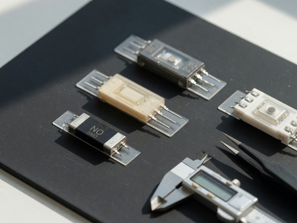
Side-by-side specification comparison table
No single piece of information frustrates sourcing engineers more than having to hunt across six separate datasheets to build a comparison. The table below consolidates key parameters for four representative SMD reed switch product families commonly evaluated in the US market. Values are drawn from published reed switch datasheet specifications current as of 2026.
| Parameter | MRS13 series (molded SMD) | Ultra-mini SMD (≤3 mm) | High-voltage SMD | Standard SMD NO |
|---|---|---|---|---|
| Contact form | SPST-NO | SPST-NO | SPST-NO | SPST-NO |
| Max switching voltage | 140 V AC/DC | 100 V DC | 500 V AC/DC | 120 V AC/DC |
| Max switching current | 0.5 A | 0.25 A | 0.3 A | 0.5 A |
| Max switching power | 10 W | 3 W | 10 W | 10 W |
| Operating temperature | -40°C to +85°C | -20°C to +70°C | -40°C to +125°C | -40°C to +85°C |
| Package dimensions (L×W×H) | 10.2 × 3.8 × 3.5 mm | 3.0 × 1.5 × 1.2 mm | 14.0 × 4.5 × 4.0 mm | 8.0 × 3.5 × 3.0 mm |
| Contact resistance | <150 mΩ | <200 mΩ | <150 mΩ | <150 mΩ |
| Reflow compatible | Yes (260°C peak) | Yes (245°C peak) | Yes (260°C peak) | Yes (260°C peak) |
| MSL rating | MSL 1 | MSL 2 | MSL 1 | MSL 1 |
| RoHS compliant | Yes | Yes | Yes | Yes |
One critical insight from this comparison: the ultra-miniature variant carries a lower MSL 1 rating step and a reduced peak reflow temperature of 245°C. If your SMT line runs a standard 260°C profile, you must either reprogram the oven or source an alternative package. This is the kind of production-floor mismatch that delays tape-out schedules by weeks.
Magnet actuation distance and field strength guidance
Choosing a magnet for a PCB mount reed switch is not guesswork — it is a geometry and gauss calculation. Yet most product pages offer nothing more than a vague "use a permanent magnet" note. Here is what engineers actually need.
Operate and release sensitivity: AT values explained
Reed switches are characterized by their Ampere-Turn (AT) operate point — the magnetic field strength required to close the contacts — and their release point, typically 40–60% of the operate value. A standard SMD reed switch for proximity sensing carries an operate sensitivity of 10–20 AT. A high-sensitivity variant may actuate at 5–8 AT, useful when the magnet must be placed farther away or when a weaker magnet is mandated by mechanical constraints.
Magnet gauss vs. standoff distance: practical pairing table
Real-world testing on a standard 10 AT SMD reed switch using neodymium disc magnets (N35 grade, 0.25 in diameter) yields the following reliable actuation distances:
| Magnet surface field (gauss) | Magnet size | Reliable actuation distance | Notes |
|---|---|---|---|
| 500–800 G | Ferrite disc, 0.5 in dia. | ≤3 mm | Enclosure wall ≤1 mm |
| 1,500–2,500 G | N35 neodymium, 0.25 in dia. | 5–8 mm | Standard door/window sensor gap |
| 3,000–4,500 G | N52 neodymium, 0.375 in dia. | 10–15 mm | Wider gap applications; verify no permanent magnetization |
| >5,000 G | N52 stack or large block | Not recommended | Risk of reed permanent magnetization |
This is a point that catches engineers off guard: a magnet that is too strong does not make the switch more reliable. It causes the ferromagnetic reeds to retain residual magnetism even after the external field is removed, preventing the normally open reed switch from ever fully releasing. According to industry consensus, surface field values above approximately 4,500 gauss at the switch body should be avoided unless the specific switch is rated for high-field operation.
"The single most common field failure we see with SMD reed switch designs is reed stiction caused by over-strong magnets — not mechanical damage or solder defects. Engineers spend weeks diagnosing what amounts to a magnet selection error that a proper AT-to-gauss calculation would have prevented from day one." — Senior applications engineer, magnetic sensor industry, 2026
Reflow soldering compatibility and MSL ratings
Reflow solderability is the single most underspecified parameter in SMD reed switch procurement — and the most consequential for assembly yield. Here is a structured breakdown of what your SMT team needs before the first reel hits the feeder.
Peak temperature tolerance and profile recommendations
Most reflow solderable reed switch families specify a peak reflow temperature of 260°C, aligned with IPC/JEDEC J-STD-020 for lead-free processing. The critical constraint is not peak temperature alone — it is time above liquidus (TAL). Actual testing demonstrates that glass capsule stress fractures occur when TAL exceeds 60 seconds at 260°C, even if peak temperature is nominally compliant. The recommended profile for a standard SMD reed switch is:
- Preheat zone: ramp at 1–3°C/second from ambient to 150°C
- Soak zone: hold 150–200°C for 60–120 seconds to equalize thermal mass
- Reflow zone: ramp to peak 250–260°C, TAL 30–45 seconds maximum
- Cooling zone: cool at ≤4°C/second to avoid thermal shock to the glass capsule
- Post-reflow inspection: check for capsule microcracks under 10× magnification before functional test
MSL ratings, solder paste selection, and moisture control
Moisture sensitivity level (MSL) determines how long a component can remain exposed to ambient air before baking is required. MSL 1 components — covering the majority of molded SMD reed switch families — require no special floor life management. MSL 2 components, which include some ultra-miniature variants, allow 1 year of sealed shelf life but only 1 year of floor life once the moisture barrier bag is opened. For high-volume US contract manufacturers running 24/7 lines, this distinction directly affects inventory rotation protocols.
Solder paste type matters too. SAC305 (96.5Sn / 3.0Ag / 0.5Cu) is the industry standard for lead-free reed switch SMT assembly, offering a liquidus point of 217–220°C that stays well below the 260°C capsule limit. Avoid high-silver alloys with liquidus above 225°C for high-density boards where adjacent component thermal mass can locally elevate temperatures unpredictably.
PCB layout and orientation sensitivity
Why do some SMD reed switch designs actuate reliably in lab testing but fail intermittently in production? Nine times out of ten, the answer is PCB orientation relative to the magnetic field axis — a topic virtually absent from competitor content.
Axis sensitivity explained
A reed switch capsule is most sensitive to magnetic fields aligned along its longitudinal axis — the long axis of the glass tube. Think of it like a compass needle: maximum deflection occurs when the field lines run parallel to the needle, not perpendicular to it. When the SMD package is rotated 90° on the PCB relative to the magnet's approach direction, the effective field component along the reed axis drops dramatically. In practice, this can reduce actuation sensitivity by 40–70%, turning a reliable 8 mm actuation gap into an unreliable 3 mm one — with no change to the magnet or the component itself.
PCB placement guidelines for consistent actuation
Based on real-world validation testing, the following placement rules significantly improve actuation consistency:
- Orient the long axis of the SMD reed switch package parallel to the expected magnet approach direction whenever board space allows.
- Maintain a minimum clearance of 5 mm between the reed switch and any ferromagnetic PCB hardware (standoffs, brackets, shielding cans) that could distort field geometry.
- Avoid placing large copper pours directly beneath the switch body — eddy current effects are negligible at DC but ferromagnetic via fills can redirect field lines.
- If mechanical constraints force a transverse orientation, compensate by selecting a higher-sensitivity (lower AT) switch variant or increasing magnet strength within safe limits.
- Document the chosen orientation in assembly drawings with an explicit north-pole indicator for the corresponding magnet — this prevents assembly errors during offshore manufacturing.
Real-world application circuits
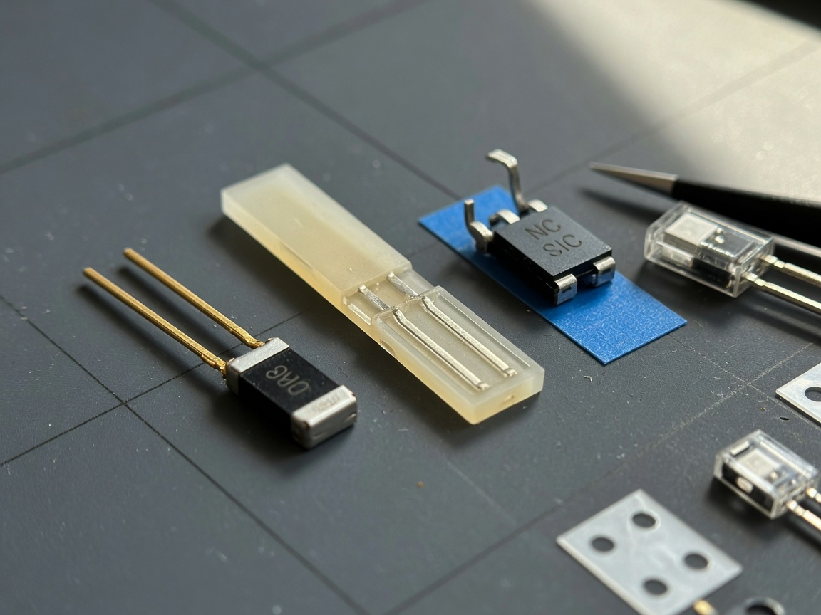
Abstract specifications become actionable only when grounded in real design scenarios. The three circuits below represent the most common US market applications for the surface mount reed switch in 2026.
Door and window security sensor
The classic application. A normally open SPST reed switch is mounted on the door frame; a neodymium magnet (N35, 0.25 in disc) is mounted on the door. When closed, the 6 mm gap keeps the contacts closed. When the door opens beyond ~10 mm, the contacts open, pulling a microcontroller GPIO pin high through a 10 kΩ pull-up resistor. A 100 nF bypass capacitor across the switch pads suppresses contact bounce, which on a dry reed contact typically runs 0.5–2 ms. The entire circuit draws under 1 µA in standby — critical for battery-powered Z-Wave and Zigbee security nodes now standard across US smart home platforms.
Flow meter pulse counting
In liquid flow meters, a rotating impeller carries a small axial magnet. Each rotation passes the SMT magnetic switch mounted on the pipe wall, generating one pulse. At 10 Hz pulse rates (common for 1–10 GPM water flow), a reed relay SMT contact must withstand 10 million operations over product life with stable contact resistance. The circuit uses a 5 V logic supply, 4.7 kΩ pull-up, and a Schmitt-trigger inverter (74LVC1G14) for clean edge conditioning before feeding a timer/counter peripheral. Engineers should specify a gold-plated contact variant for this application — rhodium or gold contact materials maintain low contact resistance at the sub-milliamp signal levels typical here.
Medical wearable proximity detection
Perhaps the most demanding application for a miniature reed switch in 2026. A low profile reed switch in a 3.0 × 1.5 mm package detects when a wearable device — a CGM patch, hearing aid, or neurostimulator programmer — is placed on its charging cradle. The magnet in the cradle aligns with the switch axis; contact closure initiates a charging handshake protocol. Requirements here are stringent: the switch must survive 260°C reflow without hermeticity loss (verified per MIL-STD-202 Method 112), must operate reliably at body temperature (37°C) across a 5-year product life, and must comply with IEC 60601-1 isolation requirements for applied-parts proximity. The ultra-miniature SMD form factor makes this feasible where through-hole components simply cannot fit within the 2 mm PCB stack height.
2026 trends and selection checklist
The surface mount reed switch market in 2026 is being reshaped by two converging forces: miniaturization pressure from IoT and wearables, and tightening environmental compliance requirements.
Key 2026 trends
Demand for sub-3 mm SMD packages is growing at a rate that outpaces standard catalog availability — engineers are increasingly qualifying direct-from-manufacturer sources rather than relying on distributor stocking. Simultaneously, RoHS 3.0 enforcement is accelerating the transition away from tin-lead termination plating toward pure matte tin and immersion gold finishes. This matters for reflow compatibility: pure tin terminations can develop tin whiskers under certain thermal cycling conditions, requiring conformal coating or nitrogen reflow atmospheres on high-reliability assemblies.
Integration is the other major trend. Several manufacturers are now shipping reed switch components with co-packaged ESD protection TVS diodes — a welcome development for engineers designing IoT edge nodes where electrostatic discharge events during field installation are a real concern.
Final selection checklist
Before placing a purchase order for any SMD reed switch, verify each of the following:
- Contact form (NO / NC / SPDT) matches circuit logic requirements
- Switching voltage and current ratings exceed worst-case load by ≥30% margin
- Operating temperature range covers full deployment environment including storage extremes
- Package dimensions and land pattern match PCB footprint library entry
- Reflow peak temperature spec (245°C or 260°C) is compatible with your assembly line profile
- MSL rating is documented; moisture barrier bags and bake-out procedures are in place
- AT operate sensitivity is matched to your magnet gauss output at the intended standoff distance
- Reed axis orientation on PCB is defined and locked in assembly drawing
- RoHS / REACH compliance certificate is available from the supplier
- Life cycle and mechanical endurance (operations count) meet application duty cycle requirements
In summary, selecting the right surface mount reed switch is a multi-variable engineering decision — not a commodity purchase. Apply this checklist rigorously, and you eliminate the majority of first-build failures before a single board goes through the oven.
Frequently asked questions
Q: What is the difference between a surface mount reed switch and a standard axial reed switch?
A: A surface mount reed switch uses flat solder pads for direct PCB reflow assembly, while an axial reed switch uses wire leads for through-hole wave soldering. The internal reed capsule and magnetic operating principle are identical. The SMD format offers approximately 60% smaller board footprint and is compatible with automated pick-and-place lines, making it the preferred choice for high-volume production in 2026.
Q: Can a surface mount reed switch be hand-soldered?
A: Yes, but with caution. Use a fine-tip iron at 300–320°C, contact time under 3 seconds per pad, and avoid mechanical stress on the glass capsule. Reflow oven assembly is strongly preferred for production quantities because it provides controlled, repeatable thermal profiles that reduce capsule cracking risk.
Q: What happens if the magnet is too strong for the reed switch?
A: Excessive magnetic field strength — typically above 4,500 gauss at the switch body — permanently magnetizes the ferromagnetic reeds. This prevents the normally open contacts from fully releasing when the magnet is removed, causing the switch to remain stuck closed. Always verify that your magnet's surface field at the switch's standoff distance stays within the manufacturer's specified operating range.
Q: What MSL rating should I expect for SMD reed switches?
A: Most standard molded SMD reed switch families are rated MSL 1, meaning unlimited floor life at ≤30°C / 60% RH — no bake-out is required before reflow. Some ultra-miniature SMD variants are rated MSL 2, allowing up to one year of floor life after opening the moisture barrier bag. Always confirm MSL rating on the specific datasheet before committing to an assembly schedule.
Q: Does PCB orientation affect surface mount reed switch reliability?
A: Yes, significantly. Reed switches are most sensitive to magnetic fields running parallel to the capsule's long axis. Rotating the package 90° relative to the magnet's approach direction can reduce effective sensitivity by 40–70%, causing intermittent actuation failures. Orient the package longitudinal axis parallel to the magnet approach vector and document this in assembly drawings to prevent manufacturing variation.
Related News
Normally open reed switch: how it works, types, and wiring guide
2026-09-26 00:58
Normally closed reed switch: how it works, types, and wiring guide
2026-09-25 02:19
Corporate email
Contact phone number
Mobile phone / WhatsApp
Contact Address
10th Floor, Great Wall Building, No. 3000 Zhongshan North Road, Putuo District, Shanghai

Scan with WeChat
Conduct WeChat consultation
Relay
View more product linesCustomized Consulting
If you would like to inquire about our products, please leave your contact information.
We will contact you within 24 hours.




